Rotor to undergo coiling and process of performing coiling on rotor

A winding and rotor technology, applied in the field of rotors, can solve the problems of low winding efficiency, easy running out of wires, and high scrap rate, and achieve the effects of convenient winding, firm fixation, and improved work efficiency.

Inactive Publication Date: 2016-10-26
宁波普林斯电机有限公司
View PDF6 Cites 0 Cited by
  • Summary
  • Abstract
  • Description
  • Claims
  • Application Information

AI Technical Summary

Problems solved by technology

[0004] The technical problem to be solved by the present invention is to solve the problems of low winding efficiency, high scrap rate, high noise and easy running out of the wire in the traditional technology

Method used


Image

  • Rotor to undergo coiling and process of performing coiling on rotor
  • Rotor to undergo coiling and process of performing coiling on rotor
  • Rotor to undergo coiling and process of performing coiling on rotor

Examples


Embodiment Construction

[0027] The specific implementation manners of the present invention will be further described in detail below in conjunction with the accompanying drawings and embodiments. The following examples are used to illustrate the present invention, but are not intended to limit the scope of the present invention.

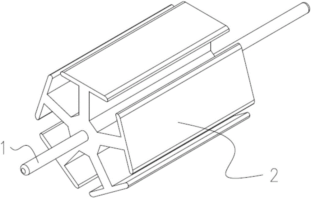
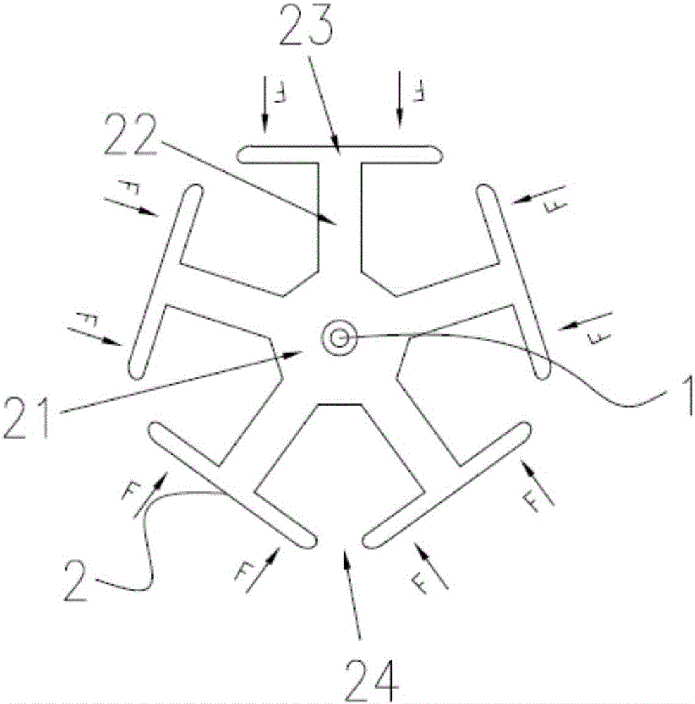
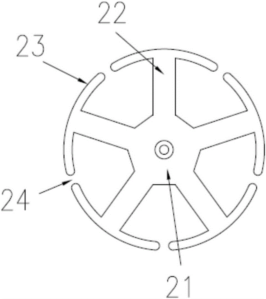
[0028] Such as figure 1 and figure 2 The shown rotor to be wound specifically includes a rotating shaft 1 and several layers of stacked rotor pieces 2; The edge is provided with a plurality of connecting pieces 22 uniformly distributed circularly along the rotating shaft 1; one end of each connecting piece 22 is connected with the mounting piece 21, and the other end is provided with a straight side 23 so that all the straight sides 23 form a regular polygon, so A notch 24 is provided between the two adjacent straight sides 23 .

[0029] Specifically, one end of the above-mentioned connecting piece 22 is located at the center of the straight side 23 and is perpendicula...


PUM


Abstract

The invention discloses a rotor to undergo coiling. The rotor comprises straight sides. The process of performing coiling on a rotor comprises the following steps of a, manufacturing rotor blades of which the integral shapes are regular-polygonal, wherein coiling openings for coiling are arranged between the straight sides of the regular polygons, and the rotor blades sleeve a rotating shaft; b, performing spraying for connecting the rotor blades and connecting the rotor blades with the rotating shaft; c, performing coiling on the rotor by an enameled wire through the coiling openings; and d, after coiling, pressing the straight side for forming an arc-shaped side through applying a pressure which moves in the rotating shaft direction on two ends of each straight side, thereby changing the integral shape of the rotor from regular-polygonal to circular. The invention discloses the rotor and a manufacture process thereof. The rotor and the manufacture process have advantages of convenient coiling, short manufacture period, high use effect and low noise.

Description

technical field [0001] The invention belongs to the technical field of a rotor, and in particular relates to a rotor to be wound and a process for winding the rotor. Background technique [0002] The shape of traditional rotor blades is generally circular, so the shape of the outer side is also an arc-shaped structure. There is a winding opening between the arc-shaped edge and the arc-shaped edge. The distance between the winding openings is generally slightly larger than the diameter of the enameled wire. . Therefore, the enameled wire can enter into the rotor sheet through the winding opening for winding. However, due to the small spacing between the winding ports, the winding is inconvenient and the work efficiency is low, and the surface of the enameled wire is easily scratched or broken by the rotor piece, so the scrap rate is high. After the winding is completed, it needs to be cured by dripping glue. Therefore, the production cycle is long, and the distance between ...

Claims


Application Information

Patent Timeline
IPC IPC(8): H02K15/09H02K15/02H02K1/26
CPCH02K15/09H02K1/26H02K15/026
Inventor 陈启
Owner 宁波普林斯电机有限公司
Why Eureka
Try Eureka