
Tape expanding device

A technology of expansion device and clamping tape, which is applied in the manufacture of electrical components, electrical solid devices, semiconductor/solid devices, etc., and can solve problems such as device damage and insufficient expansion of the adhesive tape

Active Publication Date: 2014-10-15
DISCO CORP
View PDF7 Cites 0 Cited by
  • Summary
  • Abstract
  • Description
  • Claims
  • Application Information

AI Technical Summary

Problems solved by technology

[0007] In addition, the technology of expanding the adhesive tape on which the wafer is attached as described in the above-mentioned Patent Document 2 has a problem that since it is stretched across two opposing sides of the adhesive tape, the two perpendicular sides are stretched. Shrinking side, so that the individual components attached to the adhesive tape are damaged
In addition, there is a problem that the adhesive tape does not expand sufficiently when stretching the opposing two sides while sandwiching the two perpendicular sides.

Method used


Image

  • Tape expanding device
  • Tape expanding device
  • Tape expanding device

Examples


Embodiment Construction

[0058] Hereinafter, preferred embodiments of the band expansion device according to the present invention will be described in detail with reference to the drawings.

[0059] exist Figure 11 A top view of the adhesive tape expanded by the tape expansion device is shown in . The illustrated adhesive tape 1 is formed into a square (rectangular), and includes: a first side 1a; a second side 1b, which is opposed to the first side 1a; a third side 1c, which is opposite to the first side 1a and The second side 1b is perpendicular; and the fourth side 1d is opposed to the third side 1c. An adhesive layer is coated on the surface of the adhesive tape 1 formed in this way, and the wafer 10 is stuck to the center part of the surface. Furthermore, regarding the wafer 10, in the illustrated embodiment, a plurality of partitions 101 are formed in a lattice shape on the surface 10a, and the wafer 10 is formed in a plurality of regions divided by the plurality of partitions 101, respectiv...


PUM


Abstract

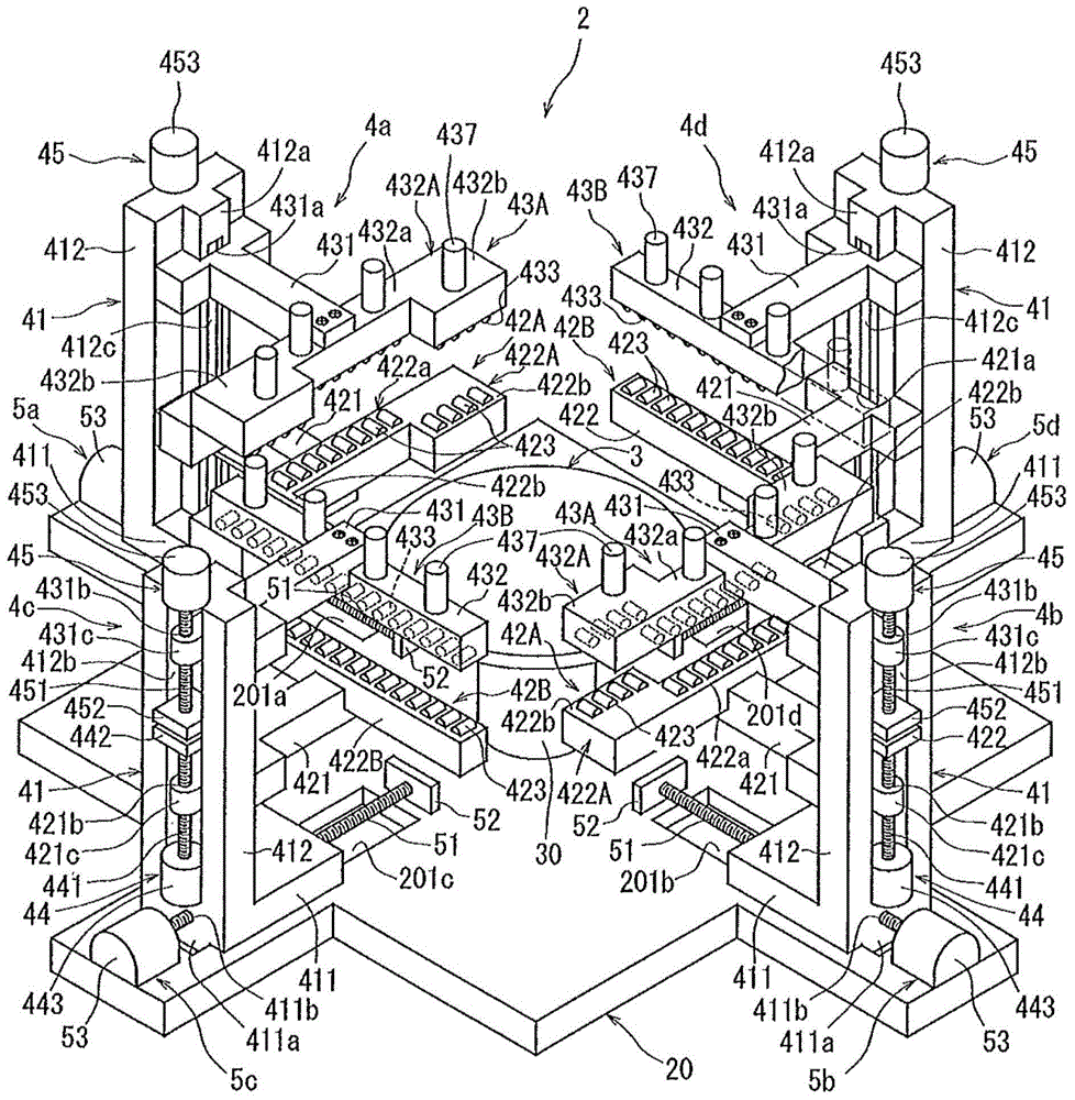
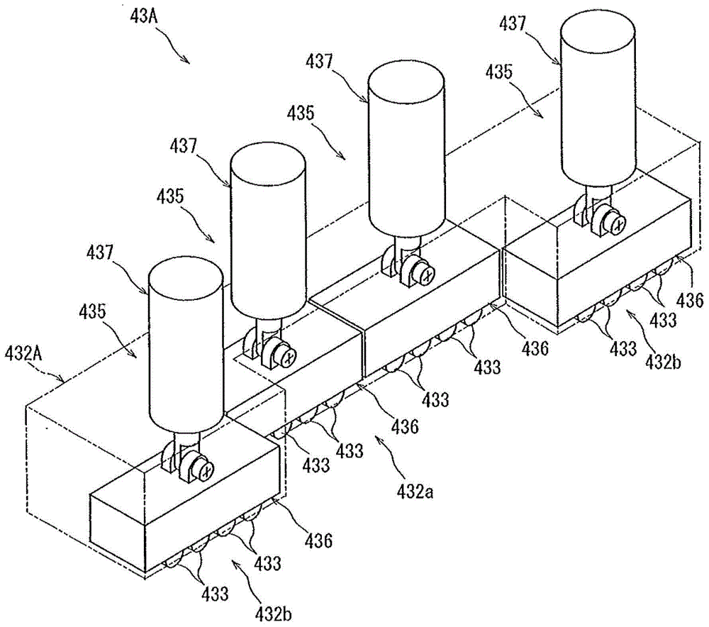
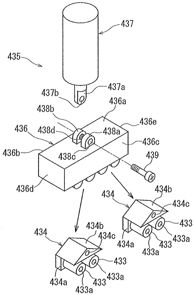
A tape expanding device, even opposite two sides of a splicing tape are clamped to perform extending, so as to expand the splicing tape, perpendicular two sides cannot narrow, and the splicing tape can be fully expanded even in the state of clamping the perpendicular two sides. The tape expanding device comprises: a first clamping member for clamping a first side of the tape; a second clamping member for clamping a second side opposite to the first side; a third clamping member for clamping a third side perpendicular to the first side; a fourth clamping member for clamping a fourth side opposite to the third side; and an expanding member for enabling the first to fourth clamping members to respectively move in the directions perpendicular to the clamped sides, wherein the first to fourth clamping members respectively comprise a lower side clamping mechanism and an upper side clamping mechanism, an upper part of the lower side clamping mechanism is provided with a plurality of rollers, a lower part of the upper side clamping mechanism is provided with a plurality of rollers, in the first and second clamping members and / or third and fourth clamping members, the lower side and upper side clamping mechanisms consist of center clamping regions and end clamping regions, the end clamping regions are respectively configured to protrude towards the opposite side compared with the center clamping regions.

Description

technical field [0001] The present invention relates to a tape expanding device for expanding an adhesive tape on which a wafer is attached to apply an external force to the wafer. Background technique [0002] In the manufacturing process of a semiconductor device, a plurality of regions are divided on the surface of a substantially disk-shaped semiconductor wafer by dividing lines called streets arranged in a grid pattern, and ICs (Integrated Circuit ICs) are formed in the divided regions. : integrated circuits), LSI (Large-scale Integration: large-scale integrated circuits) and other devices. Then, by cutting the semiconductor wafer along the lanes, the region in which the device is formed is divided, and individual devices are manufactured. In addition, the optical device wafer formed by laminating gallium nitride-based compound semiconductors on the surface of the sapphire substrate is also divided into individual optical devices such as light-emitting diodes and laser...

Claims


Application Information

Patent Timeline
IPC IPC(8): H01L21/78
CPCH01L21/6836H01L21/78H01L2221/68336
Inventor 关家一马高泽徹
Owner DISCO CORP
Learn More