
Range gating super-resolution three-dimensional imaging method based on spatial differencing shaping

A super-resolution and spatial difference technology, applied in measurement devices, instruments, surveying and navigation, etc., can solve the problem of limited range resolution, high range resolution relying on high-performance devices, range-gated super-resolution 3D imaging range resolution rate-dependent time-domain characteristics, etc., to achieve the effect of reducing the requirements of pulse width time-domain characteristics

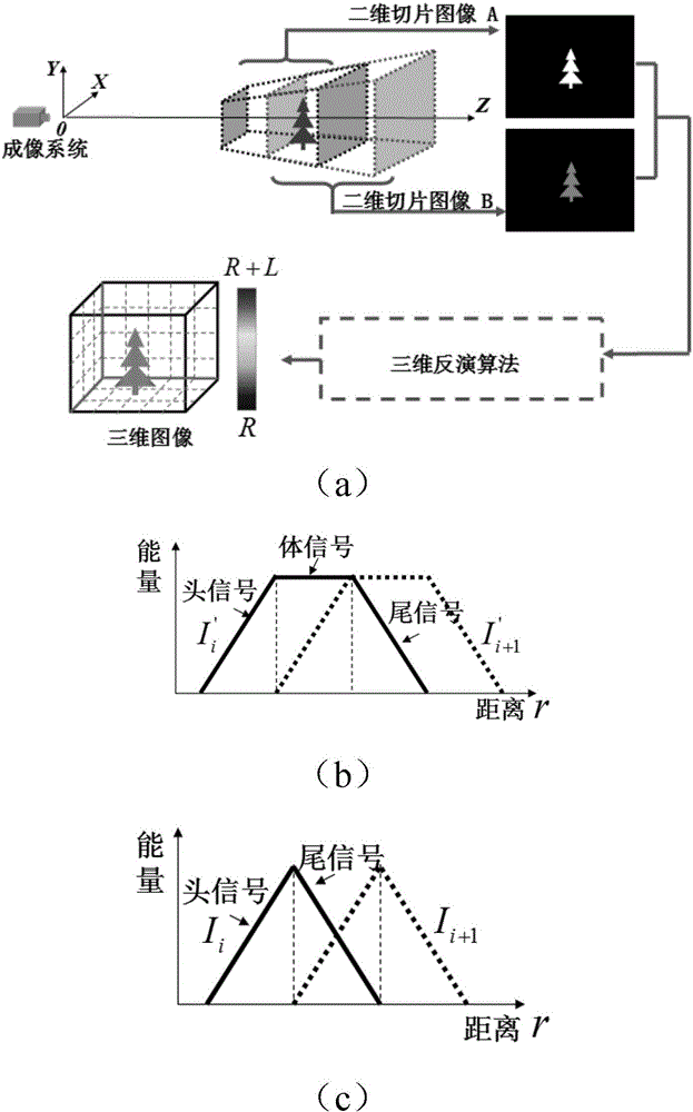
Active Publication Date: 2014-10-15
北京中科盛视科技有限责任公司
View PDF6 Cites 5 Cited by
  • Summary
  • Abstract
  • Description
  • Claims
  • Application Information

AI Technical Summary

Problems solved by technology

[0004] Although range-gated super-resolution 3D imaging solves the problem that traditional range-gated step-by-step scanning 3D imaging relies on high-performance devices for high-range resolution, it realizes the use of low-performance devices to obtain distance comparable to traditional high-performance devices. resolution, however, the range resolution of range-gated super-resolution 3D imaging depends on the temporal properties of the laser pulses
In theory, the narrower the laser pulse width, the higher the distance resolution of super-resolution 3D imaging. However, in practical applications, the laser pulse width cannot be infinitely narrowed. Each pulsed laser has a minimum pulse width, and the laser pulse width After the minimum pulse width is reached, it will no longer be narrowed, thus limiting the further improvement of distance resolution

Method used


Image

  • Range gating super-resolution three-dimensional imaging method based on spatial differencing shaping
  • Range gating super-resolution three-dimensional imaging method based on spatial differencing shaping
  • Range gating super-resolution three-dimensional imaging method based on spatial differencing shaping

Examples


Embodiment Construction

[0041] Descriptions of structural embodiments and methods of the invention are disclosed herein. It will be understood that the intention is not to limit the invention to the particular disclosed embodiments, but that the invention can be practiced using other features, elements, methods and embodiments. Similar elements in different embodiments are generally labeled with similar numbers.

[0042]A range-gated super-resolution three-dimensional imaging method based on spatial differential shaping proposed by the present invention refers to the ratio of pixel gray level and The technology of three-dimensional scene reconstruction realized by the mapping relationship between distance-energy ratios can improve the distance resolution of range-gated super-resolution three-dimensional imaging, and the distance-gated super-resolution three-dimensional imaging method based on spatial differential shaping utilizes spatial energy envelope The shaper performs spatial differential shapi...


PUM


Abstract

The invention discloses a range gating super-resolution three-dimensional imaging method based on spatial differencing shaping. The method comprises the following steps: acquiring a first slice image used for three-dimensional reconstruction; building a first space energy envelope shaper in space overlapping with the first slice image; adopting the first space energy envelope shaper to carry out space difference shaping treatment to the first slice image, so as to obtain a first new slice image; obtaining two new slice images with overlapped spaces by adopting gating delayed stepping treatment according to the former step, and carrying out range gating super-resolution three-dimensional reconstruction on the basis of the new slice images. The equivalent narrowing laser pulse durations of the new slice images are half of that of the original laser pulse duration, so that the purposes of narrowing laser pulse duration and improving range resolution are achieved. According to the method provided by the invention, the limitation of the minimal pulse duration of an impulse laser is broken, three-dimensional imaging in higher range resolution is achieved, and the application of range gating super-resolution three-dimensional imaging is developed.

Description

technical field [0001] The invention belongs to the field of laser three-dimensional imaging, in particular to a distance gating super-resolution three-dimensional imaging method based on spatial differential shaping, which can improve the distance resolution of range gating super-resolution three-dimensional imaging. Background technique [0002] Range-gated super-resolution 3D imaging technology is a new type of non-scanning 3D imaging technology, which can work effectively in environments with severe backscattering such as underwater and fog, rain, snow, etc. Obstacle avoidance navigation and other fields have broad application prospects, especially in the field of underwater three-dimensional imaging. [0003] At present, range-gated super-resolution 3D imaging technologies mainly include two types: super-resolution 3D imaging based on trapezoidal distance energy envelope (Opt.Lett., 2007, Vol.32(21), 3146-3148) and triangular distance-based Super-resolution 3D imaging ...

Claims


Application Information

Patent Timeline
Patent Type & Authority Applications(China)
IPC IPC(8): G01C11/00
CPCG01C11/00
Inventor 王新伟周燕李友福
Owner 北京中科盛视科技有限责任公司
Learn More