Convenience column cap

A column cap and convenient technology, applied in the direction of bridge parts, roads, bridges, etc., can solve the problems of wasted space and surface spray coating damage, and achieve the effect of reducing wasted space and reliable installation.

Active Publication Date: 2017-02-01
JIANGSU AIKEQING IND
View PDF6 Cites 0 Cited by
  • Summary
  • Abstract
  • Description
  • Claims
  • Application Information

AI Technical Summary

Problems solved by technology

Since the assembly requires power, it needs to be found on site after assembly in the factory. This shape wastes space and is likely to cause damage to the surface spray coating

Method used


Image

  • Convenience column cap
  • Convenience column cap
  • Convenience column cap

Examples


Embodiment Construction

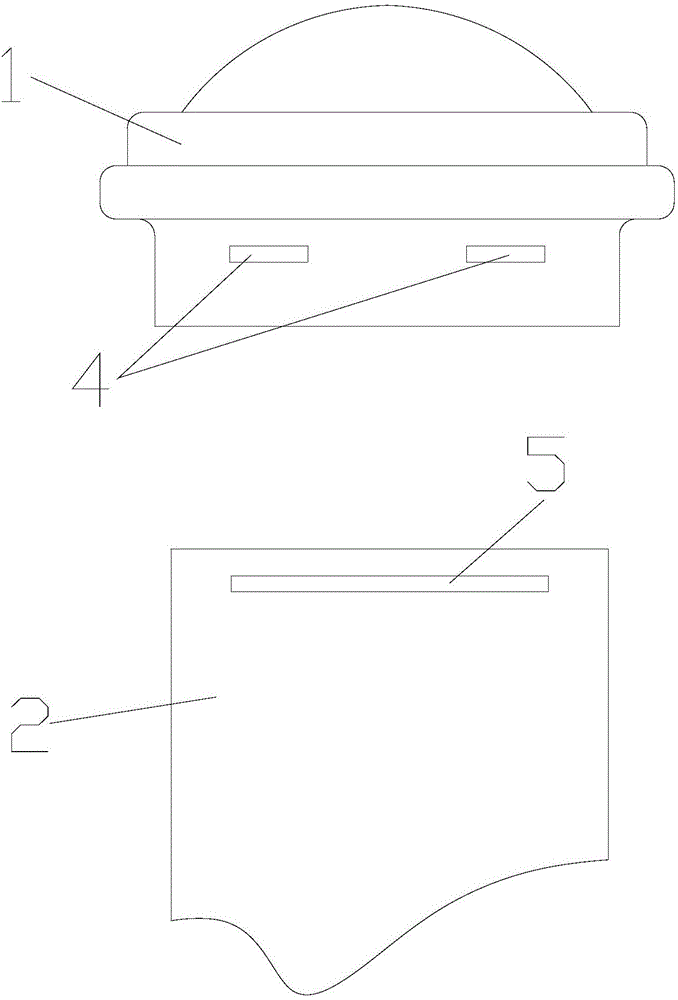
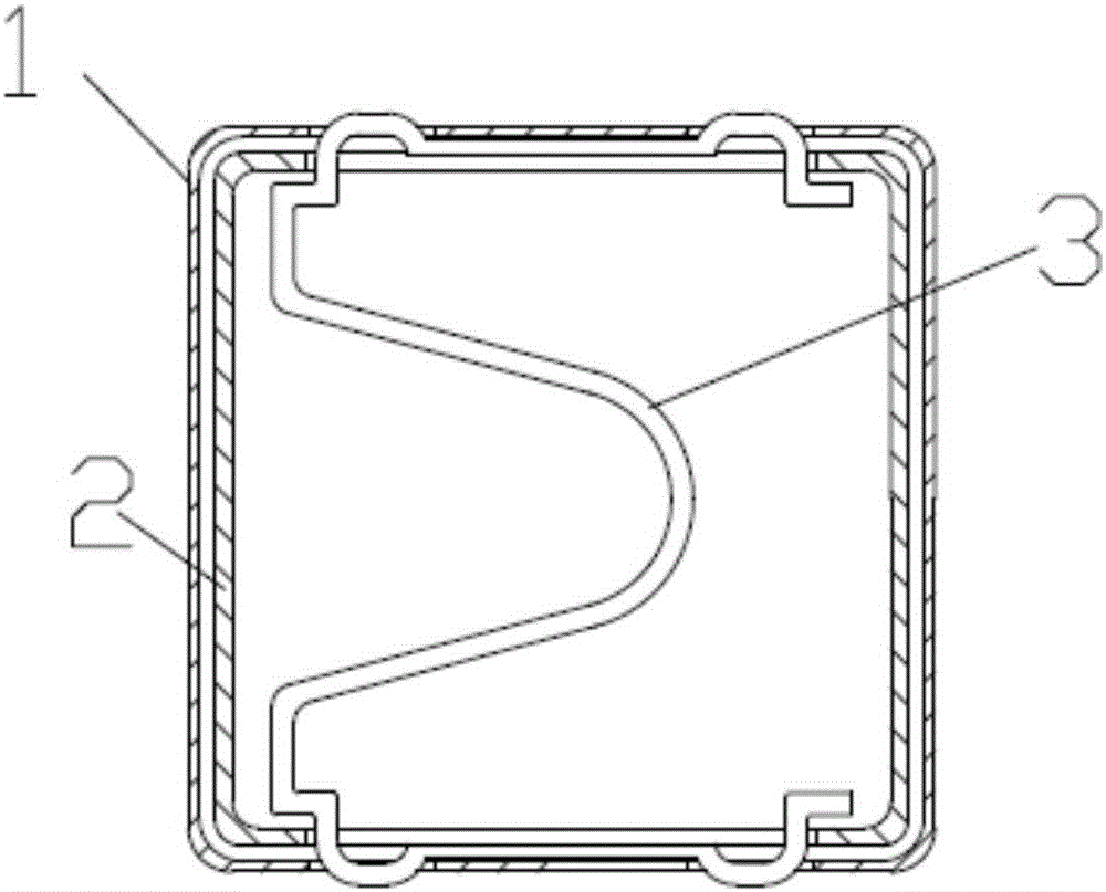
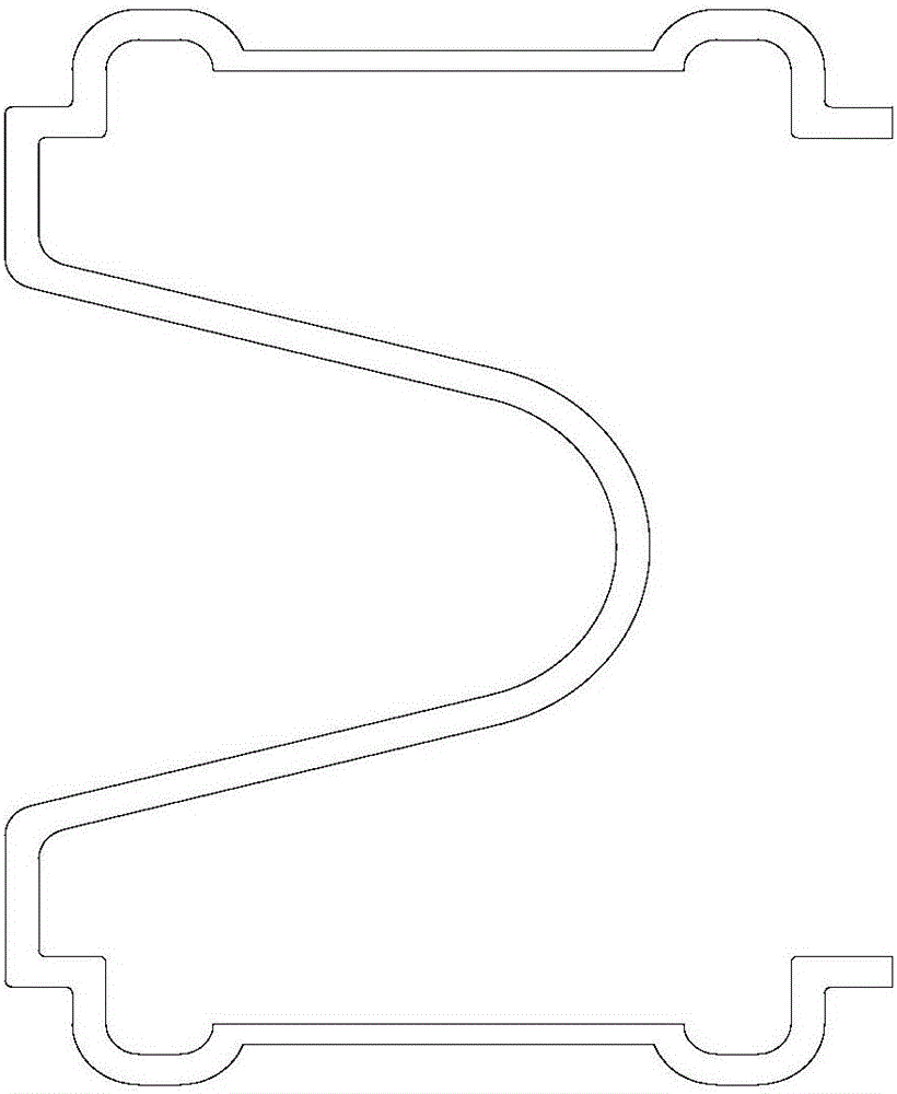
[0013] Such as Figure 1-Figure 3 As shown, a convenient column cap, the column cap 1 is integrally formed, the lower part of which is the connecting end, two small through holes 4 are arranged on one side of the connecting end, and two small through holes 4 are also arranged on the symmetrical side thereof. A small through hole 4, a large through hole 5 is provided on the steel pipe 2, the connecting end is connected to the steel pipe 2 through a column cap card 3, and one side of the column cap card 3 is arranged on the small through hole 4 of the connecting end, symmetrical to it The other side is also arranged on the small through hole at the connection end, and the column cap card 3 is M type. The two small through holes 4 are bilaterally symmetrical and are arranged on the connecting end in cooperation with the post cap card 3 . The column cap clamp 3 is clamped on the large through hole 5 of the steel pipe 2 through the protruding part of the two small through holes 4 ...


PUM


Abstract

The invention relates to a convenient post cap. The post cap is integrally molded, wherein the lower part of the post cap is a connecting end, two small through holes are formed in the connecting end, a large through hole is formed in a steel pipe, the connecting end is connected onto the steel pipe through a post cap clamp, and the post cap clamp is arranged in the small through hole of the connecting end. The invention provides the convenient post cap which is reliable to connect, is convenient to install and can be assembled on the site.

Description

technical field [0001] The invention relates to the field of guardrails, in particular to a post cap on a column of a road guardrail. Background technique [0002] Most of the existing column caps and steel pipes are fixedly connected with self-tapping screws or rivets, and the column caps will rotate around the self-tapping screws or rivets, causing the column caps to be mounted on the columns and skewed. Due to the high requirements on the size of each other, the assembly method can only be matched after the surface treatment of the parts, which is easy to cause damage to the surface coating. The iron filings in the assembly process are difficult to clean and easily cause rust. There are no anti-corrosion measures for screw or rivet joints, which are the source of corrosion. Since the assembly requires power, it needs to be found on site after assembly in the factory. This shape wastes space and is likely to cause damage to the surface spray coating. Contents of the in...

Claims


Application Information

Patent Timeline
Patent Type & Authority Patents(China)
IPC IPC(8): E01D19/10E01F15/02
Inventor 李琳
Owner JIANGSU AIKEQING IND
Why Eureka
Try Eureka