
Hybrid drive device of motor vehicle

A hybrid drive and motor vehicle technology, applied to motor vehicles, power plants, hybrid vehicles, etc., can solve problems such as system design and coolant delay, and achieve the effects of time delay avoidance, overload avoidance, and efficiency improvement

Active Publication Date: 2014-10-15
VOLKSWAGEN AG
View PDF8 Cites 14 Cited by
  • Summary
  • Abstract
  • Description
  • Claims
  • Application Information

AI Technical Summary

Problems solved by technology

This can lead to a delay in the supply of coolant to the disconnect clutch in the first operating mode or when the vehicle is started
Therefore the above system is not an optimal design

Method used


Image

  • Hybrid drive device of motor vehicle
  • Hybrid drive device of motor vehicle
  • Hybrid drive device of motor vehicle

Examples


Embodiment Construction

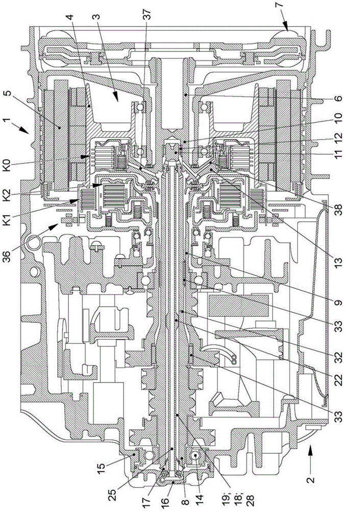
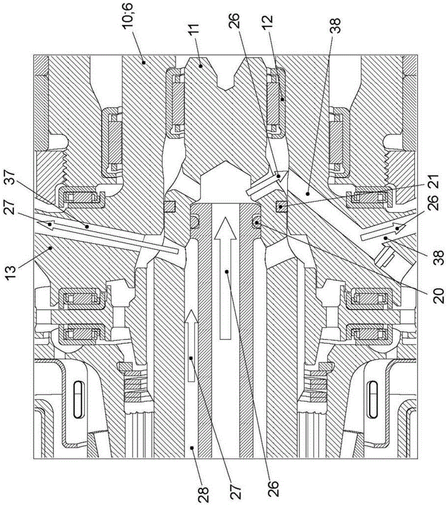
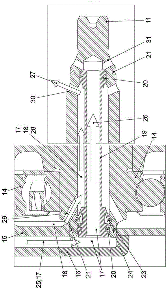
[0013] exist figure 1 The hybrid drive 1 with the dual clutch transmission 2 is clearly visible in the figure. The dual-clutch transmission 2 and the hybrid drive 1 are part of a drive train (not shown in detail) of a motor vehicle (not shown in detail). The hybrid drive 1 has an electric machine 3 . The electric motor 3 is designed as a rotary piston and has a rotatable rotor 4 and a stator 5 fastened to the housing. The electric machine 3 can work as a generator or as an electric motor.

[0014] Furthermore, the hybrid drive 1 has a drive shaft 6 . The drive shaft 6 can be driven by a (not shown) internal combustion engine. Drive shaft 6 is connected with double inertia flywheel 7. The drive shaft 6 can be functionally coupled to the rotor 4 . The drive shaft 6 can be coupled or decoupled by means of the separating clutch K0. As a result, the internal combustion engine can be coupled or decoupled by means of the separating clutch K0. The refinement is preferably desi...


PUM


Abstract

The invention relates to a hybrid drive device (1) for a motor vehicle. The hybrid drive device has a motor (3) which is provided with a rotor (4) and a stator (5). The rotor (4) has a separating clutch (K0) in which a drive shaft (6) driven by an internal combustion engine. The drive shaft (6) is coupled to the rotor (4) by means of the separating clutch (K0). At least one transmission input shaft (8, 9) is coupled to the rotor (4) via a friction clutch (K1, K2). The separating clutch (K0) and at least one friction clutch (K1, K2) are arranged in a common wet chamber (36). A coolant supply system (17) comprises a coolant pipe (18) for supplying the wet chamber (36) with a coolant (27), and wherein the coolant pipe (18) is connected into the wet chamber (36). The coolant pipe (18) accesses to the separating clutch (K0). The coolant (27) is guided and particularly can be pressed into the separating clutch (K0). Therefore, the delay for supplying the coolant (27) to the separating clutch (K0) can be prevented.

Description

technical field [0001] The invention relates to a hybrid drive for a motor vehicle with an electric machine, wherein the electric machine has a rotor and a stator, wherein the rotor is associated with a separating clutch, wherein a drive shaft drivable by an internal combustion engine is provided, wherein , the drive shaft is coupleable to the rotor by means of the disconnect clutch, wherein at least one transmission input shaft is respectively coupleable to the rotor via a friction clutch, wherein the disconnect clutch and the at least one friction clutch Arranged in a common wet room, wherein the coolant supply system has coolant lines for supplying coolant to the wet room, and wherein the coolant lines lead into the wet room. Background technique [0002] A hybrid drive for a motor vehicle is known from DE 10 2009 038 344 A1. The device is provided with an outer housing, wherein the housing defines a common wet chamber for components located therein. An electric machine...

Claims


Application Information

Patent Timeline
IPC IPC(8): B60K6/387B60K6/26B60K6/40B60K6/405F16D25/08
CPCF16D25/0638B60Y2400/428B60K2006/4825F16D13/72B60K6/387F16D48/062F16D2500/1066F16D2500/5106F16D2500/70448Y02T10/62F16D25/123F16D25/082
Inventor R.阿伦斯F.米勒
Owner VOLKSWAGEN AG
Learn More