
Encoder, production method for encoder scale, production method for encoder, and drive device

A manufacturing method and encoder technology, which is applied in the field of encoders, can solve the problems of lower yield, lower precision of pattern making, and obstruction of etching process, etc., and achieve the effect of preventing yield reduction

Active Publication Date: 2014-10-08
NIKON CORP
View PDF7 Cites 2 Cited by
  • Summary
  • Abstract
  • Description
  • Claims
  • Application Information

AI Technical Summary

Problems solved by technology

[0008] However, for example, in the case of forming a substrate using a material that dissolves in an etching solution such as untreated aluminum (such as pure aluminum), when the substrate is immersed in an etching solution, a part of the substrate is dissolved, and the dissolved aluminum remains between patterns, etc. , there are cases where it becomes an obstacle to the etching process
Therefore, there is a case where the accuracy of patterning is lowered, resulting in a lowered yield

Method used


Image

  • Encoder, production method for encoder scale, production method for encoder, and drive device
  • Encoder, production method for encoder scale, production method for encoder, and drive device
  • Encoder, production method for encoder scale, production method for encoder, and drive device

Examples


Embodiment Construction

[0028] Hereinafter, embodiments of the present invention will be described with reference to the drawings.

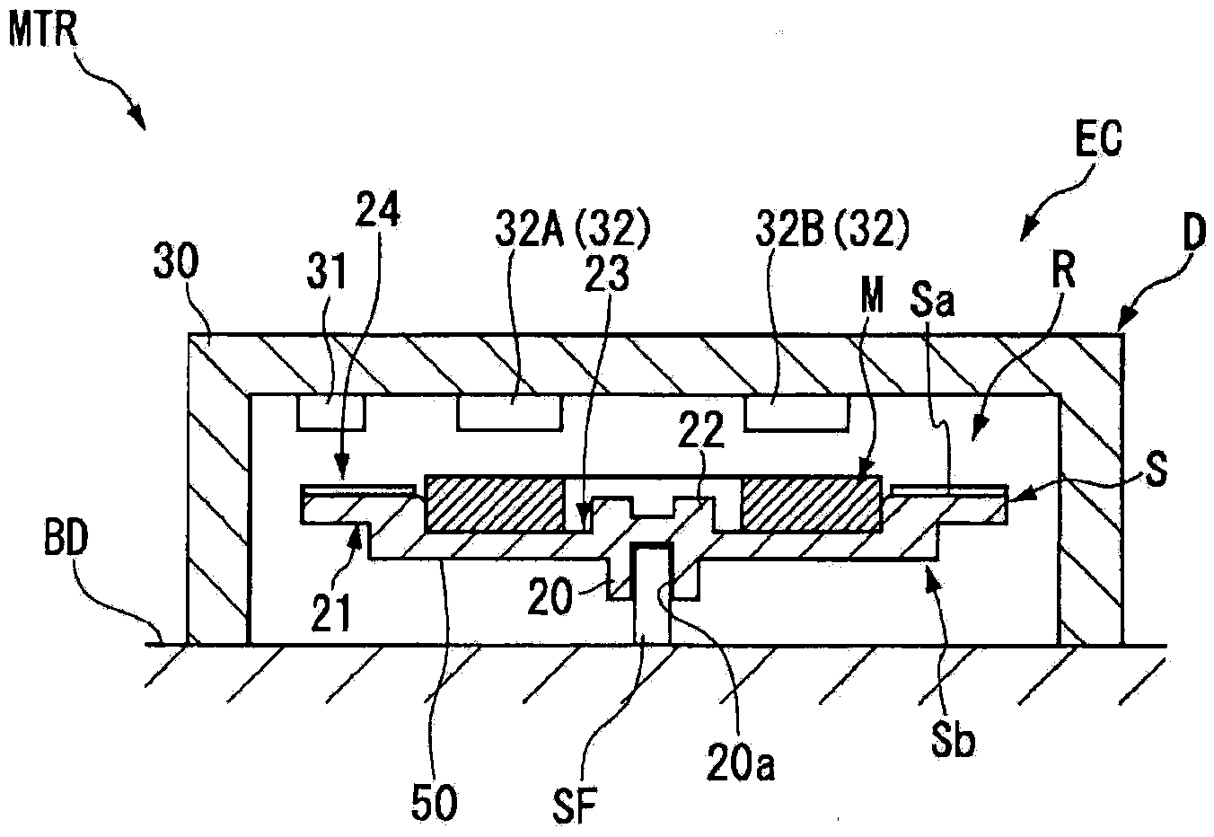
[0029] figure 1 It is a cross-sectional view showing the structure of a motor device MTR as an example of a drive device (measurement object).

[0030] Such as figure 1 As shown, the motor device MTR has: a moving body (rotor), that is, a moving shaft (rotation shaft) SF; a motor body BD that is a drive unit that rotates the rotation shaft SF; and a code for detecting movement information (for example, rotation information) of the rotation shaft SF. device EC. The encoder EC includes a scale portion (rotation portion, scale) R and a detection portion D that moves relatively to the scale portion in order to detect movement information of the moving object. The encoder EC is used in a state where the rotating unit R is accommodated in the casing 30 constituting the detecting unit D. As shown in FIG. In addition, the encoder EC of this embodiment is a structure which t...


PUM


Abstract

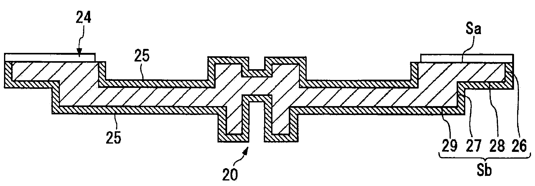
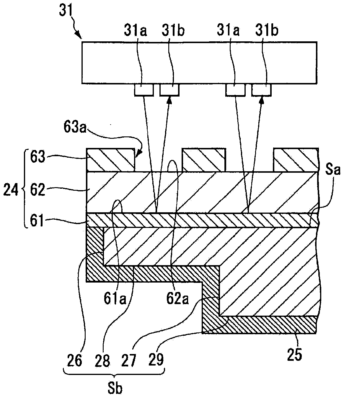
An encoder, comprising: a scale section having a base material comprising a metal material, having a pattern formed on a first surface of the base material, and having a passivation section formed on a second surface of the base material differing from the first surface; and a detection unit that moves relative to the scale section, and detects the pattern.

Description

technical field [0001] The present invention relates to an encoder, a method for manufacturing a scale for the encoder, a method for manufacturing the encoder, and a driving device. [0002] this application claims priority based on Japanese Patent Application No. 2011-287350 for which it applied on December 28, 2011, The content is used here. Background technique [0003] An encoder is known as a device for detecting rotation information such as a rotation speed, a rotation angle, and a rotation position of a rotating body including a rotation shaft of a motor. As one of such encoders, for example, a reflective optical encoder is known (for example, refer to Patent Document 1). A reflective optical encoder has, for example, a disk member having a reflective area and a non-reflective area formed on its surface, and detects the rotation information by detecting light reflected in the reflective area by a light receiving element. [0004] When manufacturing a disc member, fo...

Claims


Application Information

Patent Timeline
Patent Type & Authority Applications(China)
IPC IPC(8): G01D5/347
CPCG01D5/3473G01D5/34707G01D5/12G01D5/165H02K5/02H02K15/00
Inventor 引地新太郎杉山英明
Owner NIKON CORP
Learn More