
Distributed economic dispatch and coordination control method for micro-grid system

A technology of economic scheduling and coordinated control, applied in electrical components, circuit devices, AC network circuits, etc., can solve problems such as large communication volume, lack of reliability of power supply, and affecting the efficient and economical operation of power generation units in the microgrid

Inactive Publication Date: 2014-10-08
CHONGQING UNIV
View PDF3 Cites 26 Cited by
  • Summary
  • Abstract
  • Description
  • Claims
  • Application Information

AI Technical Summary

Problems solved by technology

[0004] The existing technology has the following disadvantages: 1) The traditional economic dispatch is carried out through a centralized computing unit, which requires the power generation and load demand information of each unit in the microgrid system, and the communication volume is very large, which affects the distributed power supply. Flexibility and "plug and play" features; 2) If there is a fault in the distributed power supply in the microgrid system, the power supply system cannot detect it in time and repair it, there will be a power outage, and the reliability of the power supply is lacking. Seriously affect the normal life of residents; 3) The traditional economic dispatch is realized by manually adjusting the power generation of the generator set by the operator according to the plan made in advance, and the energy control in the whole system is open-loop, that is, the traditional economic dispatch is Offline scheduling affects the efficient and economical operation of power generation units in the microgrid

Method used


Image

  • Distributed economic dispatch and coordination control method for micro-grid system
  • Distributed economic dispatch and coordination control method for micro-grid system
  • Distributed economic dispatch and coordination control method for micro-grid system

Examples


Embodiment Construction

[0042] The present invention will be described in further detail below in conjunction with the accompanying drawings.

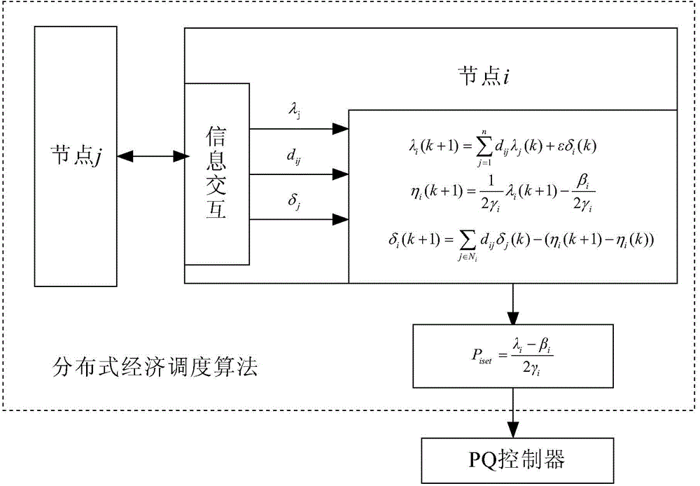
[0043] figure 1 It is a structural block diagram of a distributed microgrid system, in which the dotted line is the communication line in the microgrid system, such as figure 1 As shown, a distributed economic dispatch and coordinated control method of microgrid system uses n distributed power sources to control m loads; the first distributed power source DG1 is used as the main control unit, and the V / f control method is adopted Control so that the main control unit provides voltage and frequency references to other distributed power sources in the microgrid, and track the output power and load fluctuations of other distributed power sources through charge and discharge control; other distributed power sources (DG2~DGn) adopt The PQ control method is used to control, provide output for the micro-grid, and be responsible for the power dispatch of the micro-g...


PUM


Abstract

The invention discloses a distributed economic dispatch and coordination control method for a micro-grid system, and belongs to the technical field of distributed generation. The distributed economic dispatch and coordination control method comprises the steps that m loads are controlled by n distributed power sources; the first distributed power source is used as a master control unit, the V / f control method is adopted for control, the master control unit is made to supply voltage and frequency references to the other distributed power sources in a micro-grid, and fluctuations of output power and loads of the other distributed power sources are tracked through charging and discharging control; the other distributed power sources are controlled by the PQ control method, provide output power for the micro-grid, and are responsible for power dispatch of the micro-grid; the distributed economic dispatch algorithm is used for calculating output results of the optimum active power of all the distributed power sources. The distributed economic dispatch and coordination control method is used for controlling and coordinating the micro-grid system, so that the generation cost of the system is greatly reduced, system communication traffic is reduced, and system running reliability is ensured.

Description

technical field [0001] The invention relates to the technical field of distributed power generation, in particular to a method for distributed economic scheduling and coordinated control of a microgrid system. Background technique [0002] At present, with the rapid development of economy and society, people's demand for electricity is constantly increasing. However, conventional energy sources such as coal and oil in the world have limited resources and are increasingly polluting the atmosphere. The current energy shortage and environmental degradation force us to look for other renewable energy sources to replace the existing conventional energy sources. Therefore, distributed power generation with small capacity, low cost, and ability to provide reliable and clean energy has received more and more attention and application. Connecting distributed power generation to the large power grid in the form of a micro-grid for grid-connected operation and mutual support with the ...

Claims


Application Information

Patent Timeline
Patent Type & Authority Applications(China)
IPC IPC(8): H02J3/46H02J3/00
Inventor 陈刚冯峨宁宋永端雷云娇
Owner CHONGQING UNIV
Learn More