
Glasses for automobile driving

A technology for car driving and glasses, applied in vehicle parts, optics, instruments, etc., can solve problems such as danger, glass damage, affecting structure and strength, etc.

Inactive Publication Date: 2014-10-08
占舒婷
View PDF5 Cites 23 Cited by
  • Summary
  • Abstract
  • Description
  • Claims
  • Application Information

AI Technical Summary

Problems solved by technology

[0003] Some problems still need to be improved. Taking reversing as an example, the driver can watch the scene behind the car from the screen, but the front of the car must also be watched, otherwise it may cause the front of the car to scratch sideways, and the driver has to keep looking up and down. The pupils have an adaptation process, and the rearview mirrors on both sides must also be observed. Various angles of view need to be constantly converted. There is a process for the conversion between the real scene and the screen scene. At the same time, the problem of left and right directions must be considered. It will lead to accidents and losses, and some drivers even put their heads out of the window to observe, which is very dangerous
[0004] With the increasing number of vehicles, the problem of traffic safety is becoming more and more prominent. The problem of vehicle sight and blind spots is still a prominent issue. At present, it seems that many and large windows are indispensable. The overall structure of the car is almost difficult to change. The glass window itself is a weak link. For example, the glass is often difficult to resist the debris or stones flying from the opposite side during high-speed driving, and no buffer facilities can be attached in front of the driver. When the vehicle rolls over or falls, the glass is usually damaged first, and the door glass affects its structure. Even so, some blind spots of cars are still difficult to eliminate, for example, AB pillar blind spots, blind spots on both sides, etc. Many accidents are caused by blind spots, especially for children.

Method used


Image

  • Glasses for automobile driving
  • Glasses for automobile driving
  • Glasses for automobile driving

Examples


Embodiment Construction

[0017] The preferred embodiments of the invention will be introduced below in conjunction with the accompanying drawings.

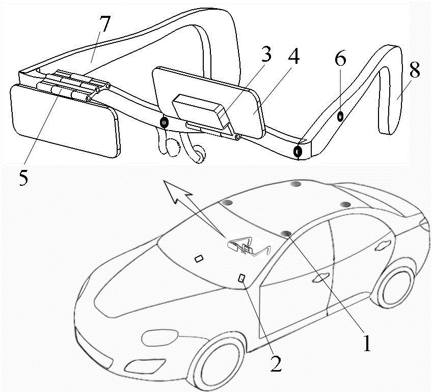
[0018] figure 1 It is a system structure diagram. The multiple cameras 1 on the top of the vehicle can take panoramic images around the vehicle. The cameras are tilted downward to eliminate the blind spots under the cameras. The head attitude detector 2 is two cameras with infrared supplementary light, which can capture There are many infrared light reflection points 6 on the spectacle frame 7, which are used as identification and positioning reference points to determine the driver’s head posture or movement. The projector 3 and the light-shielding sheet 4 are connected to the glasses through the hinge 5 On the frame 7, the two can move up and down together, and can be turned upwards respectively. The battery 8 is located at the rear of the spectacle frame, and the spectacle frame 7 has a miniature camera for shooting the eyes of the driver.

[0019] Bo...


PUM


Abstract

The invention relates to a pair of glasses for automobile driving. Cameras are installed at the roof of an automobile in all the directions, image signals are sent to a processor, a driver head posture detector is arranged in the automobile, a sensor and a miniature camera are arranged on the glasses, information is also transmitted to the processor, the processor judges the visual angle and the direction needed by a driver and processes visual angle images, and processed results are sent to the glasses, and the images are projected to the eyes of the driver through a projector located on the glasses. According to requirements of the driver, the wide-range visual angle and visual field can be provided, and even observation can be performed outside an automobile body, so that driving safety is improved, and an automobile dead zone is eliminated; conditions are provided for the improvement of the structure, the appearance and safety of the automobile, for example, the automobile and ambient conditions can be overlooked in the air, and the obtained images are as clear as pictures of an automobile game.

Description

technical field [0001] The utility model relates to a car driving glasses, belonging to the field of cars. Background technique [0002] At present, car drivers mainly observe the situation outside the car through glass windows and mirrors. Cameras and display devices can expand the observation field of view, and have been widely used as auxiliary facilities and achieved good results. [0003] Some problems still need to be improved. Taking reversing as an example, the driver can watch the scene behind the car from the screen, but the front of the car must also be watched, otherwise it may cause the front of the car to scratch sideways, and the driver has to keep looking up and down. The pupils have an adaptation process, and the rearview mirrors on both sides must also be observed. Various angles of view need to be constantly converted. There is a process for the conversion between the real scene and the screen scene. At the same time, the problem of left and right directio...

Claims


Application Information

Patent Timeline
IPC IPC(8): G02B27/01B60R1/00
Inventor 占舒婷
Owner 占舒婷
Learn More