
Amplitude compensating method used for multi-probe array imaging

An amplitude compensation, multi-probe technology, applied in the direction of using re-radiation, reflection/re-radiation of radio waves, measurement devices, etc., can solve the problems of long imaging processing time, narrow application range, unfavorable real-time imaging, etc., and achieve high-resolution imaging. The effect of saving, wide application and improving image quality

Active Publication Date: 2014-10-08
CHINA ELECTRONIS TECH INSTR CO LTD
View PDF3 Cites 5 Cited by
  • Summary
  • Abstract
  • Description
  • Claims
  • Application Information

AI Technical Summary

Problems solved by technology

There are relatively many foreign related research literatures, such as the Kirchhoff migration algorithm mentioned above, but there are the following problems: 1) The imaging processing time of the Kirchhoff migration algorithm is long, which is not conducive to real-time imaging. The amplitude compensation of this algorithm has limitations; 2) The derivation principle of the amplitude compensation method is based on the Kirchhoff migration algorithm formula, so it is only applicable to this algorithm, and is no longer applicable to other algorithms with short imaging processing time. narrow range

Method used


Image

  • Amplitude compensating method used for multi-probe array imaging
  • Amplitude compensating method used for multi-probe array imaging
  • Amplitude compensating method used for multi-probe array imaging

Examples


Embodiment 1

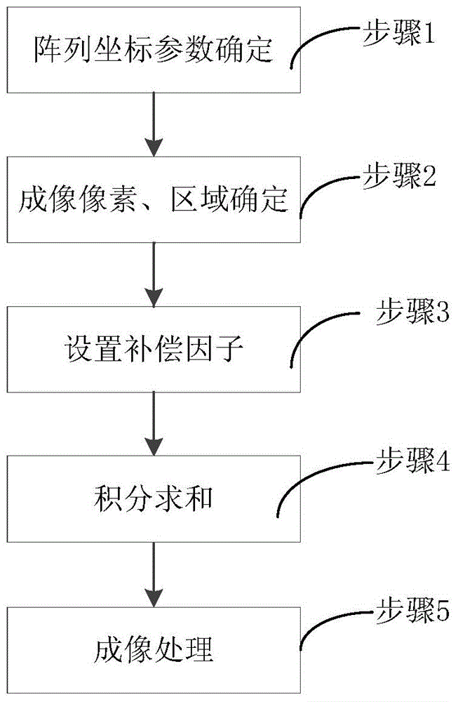
[0031] The present invention provides an amplitude compensation method for multi-probe array imaging, which includes the following steps:

[0032] Step 1: According to the layout of the multi-probe array, establish a coordinate system to determine the coordinate position of each transmitting antenna and receiving antenna;

[0033] Step 2: Determine the imaging area and pixel size according to the coordinate position of the transmitting and receiving antenna in step 1 and the relationship between Fourier transform and interpolation transformation;

[0034] Step 3: Set the compensation factor;

[0035] Step 4: The formula for calculating the new echo data after amplitude compensation is formula 1: U S =∫ S (R·R′) n UdS, where: S is the imaging area (composed of a series of pixels), R is the distance from the transmitting element to a certain pixel in the imaging area S, R' is the distance from the receiving element to a certain pixel in the imaging area S, and the U array Th...


PUM


Abstract

The invention provides an amplitude compensating method used for multi-probe array imaging. The amplitude compensating method includes the steps that proper distance correction is firstly carried out on original echo data, integration summation is carried out in an imaging area, new data are obtained, and then imaging processing is carried out. By means of the scheme, amplitude compensation of a multi-probe array is achieved under the condition that no hardware cost is increased, the imaging quality is improved, the application range is wide, and the amplitude compensating method has the huge advantages in the aspects such as high-resolution imaging and hardware resource cost saving.

Description

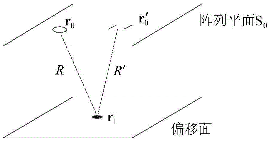
technical field [0001] The invention belongs to the technical field, and in particular relates to an amplitude compensation method for multi-probe array imaging. Background technique [0002] The schematic diagram of Kirchhoff's migration algorithm is as follows: figure 1 As shown, let the transmitting array element position vector be r 0 , the receiving element position vector is r 0 ′, R is the transmitting array element to the offset point r 1 (imaging area), R′ is the distance from the receiving element to the offset point r 1 distance, n is the normal vector of the offset surface, S 0 is the emitting element area, S 0 ' is the area of ​​the receiving element. According to the strict Kirchhoff integral equation, it can be known that the electromagnetic wave propagates from the transmitting unit to r 1 The exact expression when : [0003] U ( r 0 , t ) ...

Claims


Application Information

Patent Timeline
Patent Type & Authority Applications(China)
IPC IPC(8): G01S13/89
CPCG01S7/41G01S13/89
Inventor 胡大海杜刘革周杨赵锐殷志军刘伟颜振常庆功唐敬双年夫顺王亚海
Owner CHINA ELECTRONIS TECH INSTR CO LTD
Learn More