
Verification platform and test method for field effect transistor SOA curve

A field effect transistor and verification platform technology, which is applied in the field of field effect transistor SOA curve verification platform, can solve the problems of difficult to burn, deviation, and increased risk of burning.

Active Publication Date: 2014-10-08
XIAN SEMIPOWER ELECTRONICS TECH
View PDF6 Cites 12 Cited by
  • Summary
  • Abstract
  • Description
  • Claims
  • Application Information

AI Technical Summary

Problems solved by technology

[0002] At present, the SOA curve of field effect transistors cannot be drawn by point-by-point testing. The SOA curves provided by various manufacturers are obtained through the following indirect methods: first test the thermal resistance parameters of the product based on: thermal resistance = Δ temperature / power, use The relationship between thermal resistance, power and temperature is back calculated. The result is a theoretical value, and there will be deviations from the actual value, which will inevitably lead to burnt chips in the actual use of the client, especially when the product is used at the critical point of the SOA curve. In the region, the risk of burning chips will be greatly increased; therefore, users urgently need a platform and test method that can visually verify the electrical performance of field effect transistors at actual use parameter points

Method used


Image

  • Verification platform and test method for field effect transistor SOA curve
  • Verification platform and test method for field effect transistor SOA curve
  • Verification platform and test method for field effect transistor SOA curve

Examples


Embodiment Construction

[0024] The present invention will be further described in detail below in conjunction with specific embodiments, which are for explanation rather than limitation of the present invention.

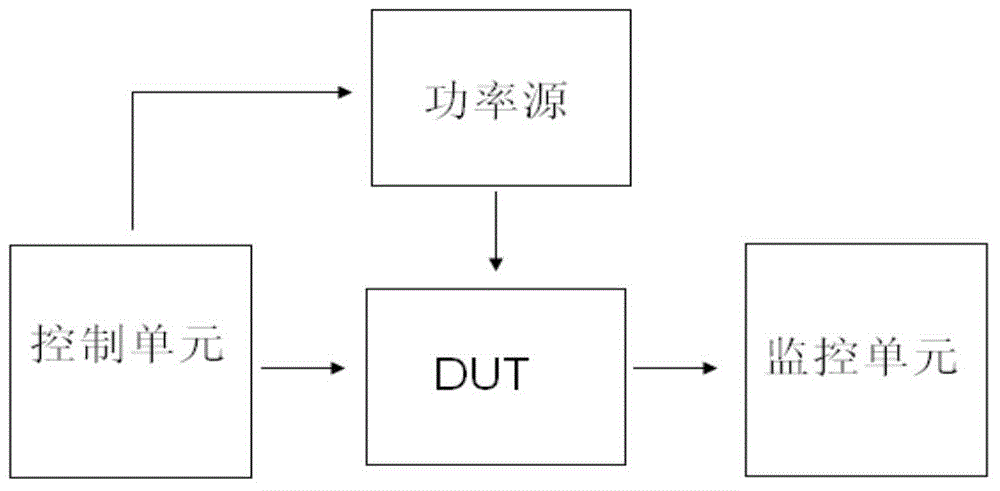
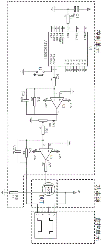
[0025] The verification platform of the SOA curve of the field effect transistor of the present invention includes a control unit, a monitoring unit for displaying the waveform of the test signal, and a power source for providing the drain voltage VD for the DUT of the device under test; the control unit includes an output The single-chip microcomputer U1 with pulse time, the switch B1 used to control the start of the platform, the first operational amplifier U2 and the second operational amplifier U3 connected in sequence, and the precision power resistor with the resistance value of 1R connected to the DUT source access terminal of the device under test R6; The input ends of the monitoring unit are respectively connected to the drain voltage VD and the voltage drop of the precision power resi...


PUM


Abstract

The invention discloses a verification platform for a field effect transistor SOA curve. The verification platform comprises a control unit, a monitor unit and a power source. The control unit comprises a single-chip microcomputer, a switch, a first operational amplifier and a second operational amplifier which are sequentially connected, and a precise power resistor which is connected with the source electrode access end of a device to be tested and has the resistance value 1R. The input end of the monitoring unit has access to the drain electrode voltage and the voltage drop of the precise power resistor. The serial input port of the single-chip microcomputer is connected with the switch with one end grounded, and the serial output port of the single-chip microcomputer is connected with the reverse input end of the first operational amplifier through a second resistor. The output end of the first operational amplifier is connected with the reverse input end of the second operational amplifier. The output end of the second operational amplifier is connected with the grid electrode access end of the device to be tested through a seventh resistor. The output end of the first operational amplifier is connected with one fixed end of a variable resistor, and the other fixed end of the variable resistor is grounded. The adjustment end of the first operational amplifier is connected to the reverse input end of the second operational amplifier through a fourth resistor. A test method for the SOA curve based on the verification platform includes the following steps of presetting values and carrying out the test.

Description

Technical field [0001] The invention relates to the test of field effect transistors, in particular to a verification platform and a test method for the SOA curve of field effect transistors. Background technique [0002] At present, the SOA curve of field effect transistors cannot be drawn by point-by-point testing. The SOA curves provided by various manufacturers are obtained through the following indirect methods: first test the product thermal resistance parameters based on: thermal resistance = Δ temperature / power, use The relationship between thermal resistance, power, and temperature is back-calculated. The result is a theoretical value, which will deviate from the actual value, which will inevitably cause burn-in in the actual use of the client, especially when the product is used in the critical SOA curve. In the area, the risk of burning chips will be greatly increased; therefore, users urgently need a platform and test method that can intuitively verify the electrical ...

Claims


Application Information

Patent Timeline
Patent Type & Authority Applications(China)
IPC IPC(8): G01R31/26
Inventor 罗景涛
Owner XIAN SEMIPOWER ELECTRONICS TECH
Learn More