Outlet air velocity remote control measurement system outside the furnace for boiler once-through burner

A measurement system and burner technology, which are applied in fluid velocity measurement, velocity/acceleration/impact measurement, and measurement devices, etc., can solve problems such as the wind velocity that cannot represent the nozzle section, occupational health hazards for measurement personnel, and high noise, and achieve the measurement method. Simple and accurate, improve the level of occupational health, reduce the effect of work intensity

Active Publication Date: 2017-02-15
STATE GRID CORP OF CHINA +1
View PDF7 Cites 0 Cited by
  • Summary
  • Abstract
  • Description
  • Claims
  • Application Information

AI Technical Summary

Problems solved by technology

When the furnace is in a ventilated state, the dust content and the noise generated by wind friction are very large, which poses a hazard to the occupational health of the surveyors, and are all operated at high altitudes, which is dangerous
Later, it was improved to fix a small standard pitot tube in the central area of ​​each spout for measurement. This measurement method does not require professionals to enter the furnace for measurement, but the obtained data is a wind speed value at the center of the spout. Since most of the air ducts are arranged with baffles and elbows, and are close to the nozzle, the wind speed values ​​at various points on the nozzle section have large differences, so the central point cannot represent the wind speed of the entire nozzle section

Method used


Image

  • Outlet air velocity remote control measurement system outside the furnace for boiler once-through burner
  • Outlet air velocity remote control measurement system outside the furnace for boiler once-through burner
  • Outlet air velocity remote control measurement system outside the furnace for boiler once-through burner

Examples


Embodiment Construction

[0020] The implementation of the present invention will be described in further detail below in conjunction with the accompanying drawings. The following embodiments are only descriptive, not restrictive, and cannot limit the protection scope of the present invention.

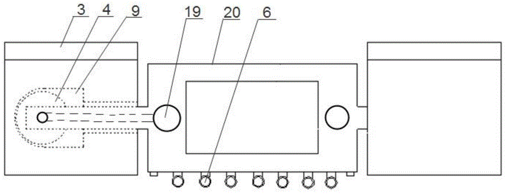
[0021] A remote control measurement system outside the furnace for the outlet wind speed of the boiler once-through burner, such as figure 1 Or as shown in 2, including two guide rail brackets with completely symmetrical structures on the left and right, the anemometer is installed on the guide rail between the left and right guide rail brackets,

[0022] Wherein, the guide rail support includes a bracket base 11 for positioning and leveling. The guide rail body is fixed on the base. In the middle of the guide rail body, a cylindrical track cavity 9 that is vertically upward and opened on one side is formed. On the inner wall of the track cavity, a spiral track 2 is formed from bottom to top, a dust cover plate...


PUM


Abstract

The invention relates to a boiler direct-current burner outlet air speed external remote control and measuring system. The system comprises a left rail support and a right rail support, the two rail supports are completely symmetric in structure, a guide rail between a left guide rail support and a right guide rail support is provided with an air speed measuring device, the air speed measuring device can move up and down through longitudinal rotary screws assembled on spiral rails in the rail supports, the air speed measuring device collects data through a differential pressure sensor arranged on the surface, and the collected data are processed through a processor in the shell and then displayed on a display screen. By means of a standard Pitot tube and the high-precision micro differential pressure sensor, average air speed of multiple nozzles in a boiler can be measured outside a combustion chamber in a remote control mode, measurement accuracy is high, distribution characteristics and rules of the air speed of different nozzles can be obtained, work intensity of measurement staff is lowered, the occupational health level is improved, the measuring system can be quickly installed and debugged, workers are reduced, and measurement efficiency is improved.

Description

technical field [0001] The invention belongs to the technical field of engineering measurement, in particular to a remote control measurement system outside the furnace for the air velocity at the outlet of a boiler direct current burner. Background technique [0002] The parameter measurement and optimal control of boiler primary and secondary wind speed are important means to improve boiler combustion efficiency and safe operation. In the past, the tests of wind speed measurement of the once-through burner (hereinafter referred to as the nozzle) and the characteristics of the air duct baffle plate required the test personnel to enter the temporary platform inside the combustion chamber to perform multi-point measurements on the nozzle section one by one. Although the data obtained by the measurement method are accurate, the More professionals are required to perform measurement work in the furnace for a long time. When the furnace is in a ventilated state, the dust conten...

Claims


Application Information

Patent Timeline
Patent Type & Authority Patents(China)
IPC IPC(8): G01P5/165
Inventor 王森周义刚薛泽海边疆王桂林孙国通
Owner STATE GRID CORP OF CHINA
Why Eureka
Try Eureka