Real time compensation method of rectification error in fiber gyro

A fiber optic gyroscope and real-time compensation technology, which is applied to measuring devices and instruments, can solve problems such as DC errors and achieve the effect of improving vibration performance

Inactive Publication Date: 2014-10-08
ZHEJIANG UNIV
View PDF4 Cites 4 Cited by
  • Summary
  • Abstract
  • Description
  • Claims
  • Application Information

AI Technical Summary

Problems solved by technology

Only when m=1 in the third item will cause DC error:

Method used


Image

  • Real time compensation method of rectification error in fiber gyro
  • Real time compensation method of rectification error in fiber gyro
  • Real time compensation method of rectification error in fiber gyro

Examples


specific Embodiment

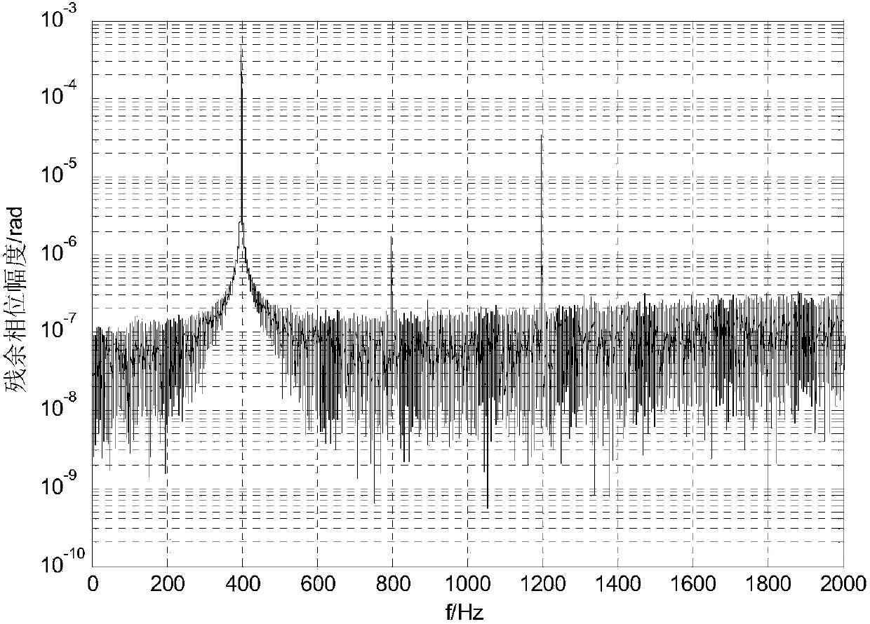
[0100] Figure 3 ~ Figure 6 Shown is the residual phase amplitude spectrum, residual phase phase spectrum, light intensity modulation term coefficient amplitude spectrum, and light intensity phase spectrum of the fiber optic gyroscope at a certain moment in the actual measurement using the method described in this patent in a 400Hz vibration environment. According to these spectral parameters, the non-reciprocal phase difference corresponding to the rectification error is calculated according to formula 15 to be 1.7762e-7rad, and the corresponding digital quantity is 0.01078. At this time, the modulation and demodulation link in the fiber optic gyroscope will subtract this value from the demodulated angular rate digital quantity, and the output angular rate digital quantity will be the value after rectification error compensation, realizing the real-time compensation of the fiber optic gyroscope rectification error.


PUM


Abstract

The invention discloses a real time compensation method of the rectification error in a fiber gyro. The method comprises the following steps: carrying out periodic square wave phase modulation and closed loop control on an optical system, carrying out analog-to-digital conversion sampling on the output signal of the optical system to obtain digital sampling values of the output signal, and synchronously demodulating to obtain a digital quantity corresponding to an angular speed; and measuring the light intensity and the residual phase in the fiber gyro in real time, carrying out spectrum analysis on the obtained light intensity and the residual phase to obtain the amplitude spectrum parameter and the phase spectrum parameter of the light intensity and the residual phase, calculating the current rectification error of the fiber gyro by using the amplitude spectrum and the phase spectrum of the light intensity and the residual phase, subtracting the obtained rectification error from the angular speed obtained through the synchronous demodulation of the fiber gyro to obtain a compensated angular speed, outputting the angular speed, and carrying out real time compensation on the rectification error. The method can compensate the rectification error of the fiber gyro in real time, and improves the vibration performance of the fiber gyro.

Description

technical field [0001] The invention relates to a signal processing method in an optical fiber gyroscope, in particular to a real-time compensation method for rectification errors in an optical fiber gyroscope. Background technique [0002] The fiber optic gyroscope is a new type of angular rate sensor, which is essentially a Segneck interferometer. According to the Segneck effect, when the fiber optic gyroscope rotates, it will introduce a phase difference proportional to the rotational angular velocity. By detecting this A phase difference can obtain the corresponding angular rate information. In order to improve the sensitivity and linearity of detection, the actual fiber optic gyroscope usually adopts square wave phase modulation and closed-loop working mode, so that the interferometer works at a fixed bias working point. When the square wave phase modulation signal used is shown in formula 1, the corresponding output signal of the fiber optic gyroscope is shown in form...

Claims


Application Information

Patent Timeline
IPC IPC(8): G01C25/00
CPCG01C25/00
Inventor 李阳陈杏藩舒晓武刘承
Owner ZHEJIANG UNIV
Why Eureka
Try Eureka