Control device and method for operating a control device

A technology for operating equipment and electrical equipment, applied in the input/output process of data processing, using mechanical devices to transfer sensing components, using electric/magnetic devices to transfer sensing components, etc., can solve problems such as wear and tear, and achieve comfortable operation, Power-saving components, the effect of precise measurement

Inactive Publication Date: 2014-10-01
ROBERT BOSCH GMBH
View PDF8 Cites 8 Cited by
  • Summary
  • Abstract
  • Description
  • Claims
  • Application Information

AI Technical Summary

Problems solved by technology

The disadvantage is that the potentiometer has a sliding contact which wears out over time

Method used


Image

  • Control device and method for operating a control device
  • Control device and method for operating a control device
  • Control device and method for operating a control device

Examples


Embodiment Construction

[0020] In different drawings, the same components are provided with the same reference signs and are therefore usually named or mentioned only once respectively.

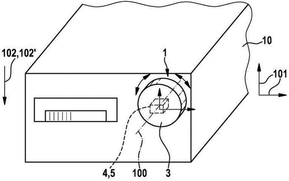
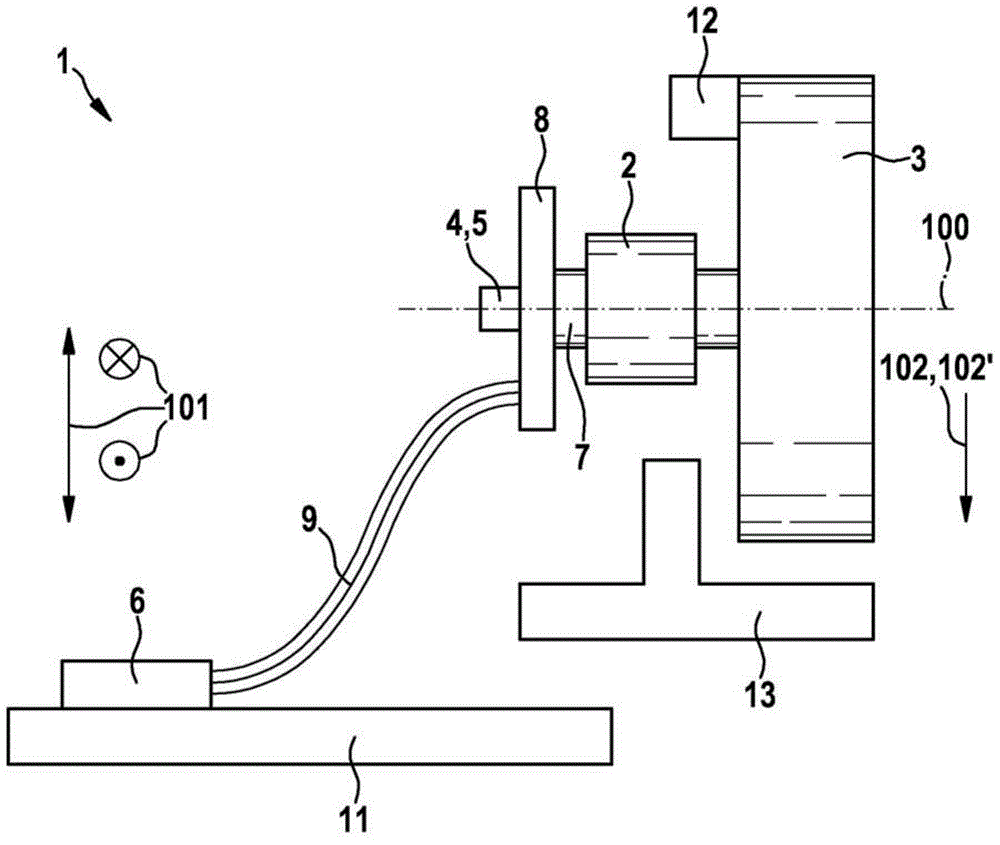
[0021] in figure 1 A schematic diagram of the operating device 1 according to the first embodiment of the present invention is shown in FIG. The operating device 1 has an operating element 3 to be manually operated by a user, which is rotatable about an operating shaft 100 relative to a basic element 2 configured as a sliding bearing. The operating element 3 is rotatably fixedly coupled to the printed circuit board 8 via a shaft 7, wherein a sensor unit 4 in the form of at least a biaxial micromechanical acceleration sensor 5 is arranged on the printed circuit board 8. The acceleration sensor 5 is coupled with the analysis and processing unit 6 through a printed circuit board 8 and a flexible electrical wire 9—for example, a flexible ribbon wire (Flexband-Leitung), where the analysis and processing unit 6 is arranged o...


PUM


Abstract

The invention relates to a control device, in particular an electrical or electronic device, which has a base element and an actuation element, which can be rotated manually relative to the base element about an actuation axis, wherein the control device also has a sensor unit for detecting a movement of the actuating element about the actuation axis and wherein the sensor unit further comprises an acceleration sensor.

Description

Technical field [0001] The invention relates to an operating device according to the preamble of claim 1. Background technique [0002] The operating device is generally known. For example, from the published document EP 0 842 822 A2, an operating button is known which has an operating element that can be rotated relative to the housing. Such knobs are used for car audio and the like, for example. The operating element is usually mechanically coupled with a potentiometer, wherein the rotary position of the knob is converted into a corresponding electrical signal by the potentiometer, in order to adjust the sound intensity of the vehicle audio, for example, by means of the knob. Disadvantageously, the potentiometer has sliding contacts, which wear out over time. Summary of the invention [0003] The operating device according to the present invention and the method for operating the operating device according to the parallel claims according to the present invention have the fol...

Claims


Application Information

Patent Timeline
Patent Type & Authority Applications(China)
IPC IPC(8): G01D5/02
CPCG01P15/00G05G1/08Y10T307/799G01B21/22H01H3/32G01V7/02G06F3/0362H01H19/14G01P15/18G01D5/12G01C3/08
Inventor F·韦格林G·拉梅尔M·弗尔斯特
Owner ROBERT BOSCH GMBH
Why Eureka
Try Eureka