Protecting method and circuit for battery module assembly and disassembly
A battery module and protection circuit technology is applied in the protection and circuit fields of battery module installation and disassembly, and can solve problems such as waste.
- Summary
- Abstract
- Description
- Claims
- Application Information
AI Technical Summary
Problems solved by technology
Method used
Image

Examples
Embodiment 1
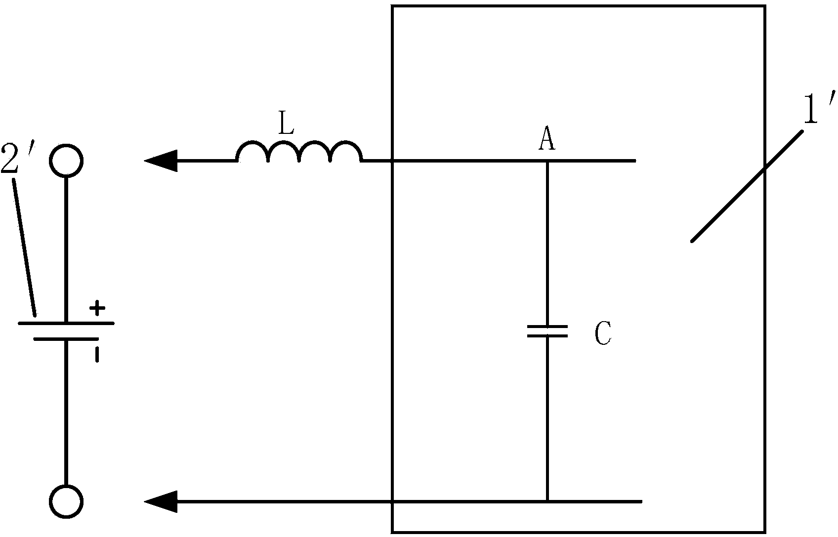
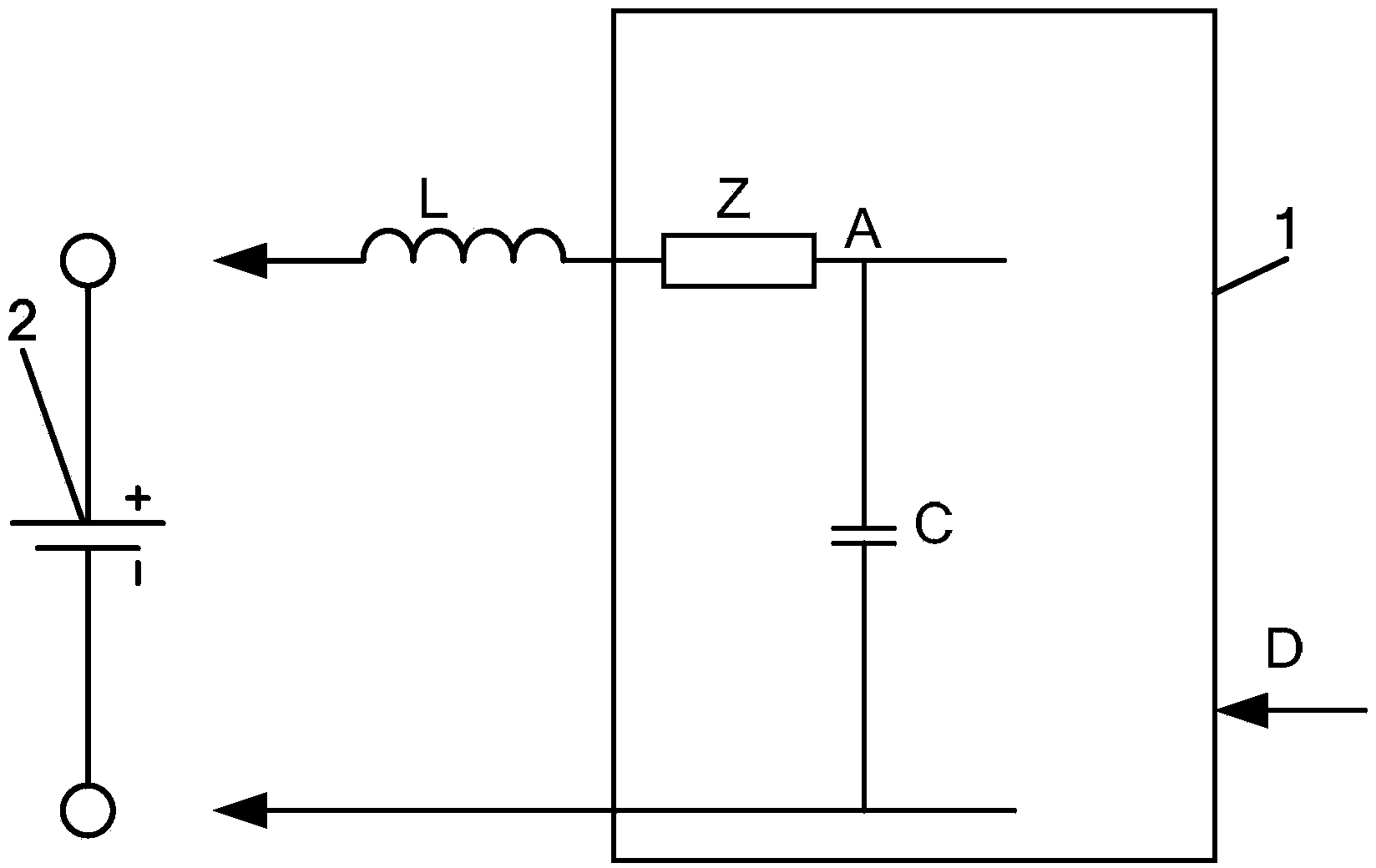
[0023] A protection method for installing and dismounting a battery module, including a battery module 1 and a battery 2, the battery module 1 and the battery 2 can be connected to form a "battery-battery module" loop, and the input capacitance C of the battery module 1 Before adding an adjustment module that can change the loop damping, when the battery module 1 and battery 2 need to be installed or disassembled, the loop damping can be increased by adjusting the adjustment module; when the battery module 1 and battery 2 are connected or the battery module 1 needs to When starting to work in high current mode, the loop damping is reduced by adjusting the adjustment module.
[0024] The adjustment mode of the adjustment module is a manual adjustment mode or a communication adjustment mode.
[0025] The adjustment module in this embodiment is a variable impedance Z. When the battery module and the battery need to be installed or disassembled, the variable impedance Z is adjuste...
Embodiment 2
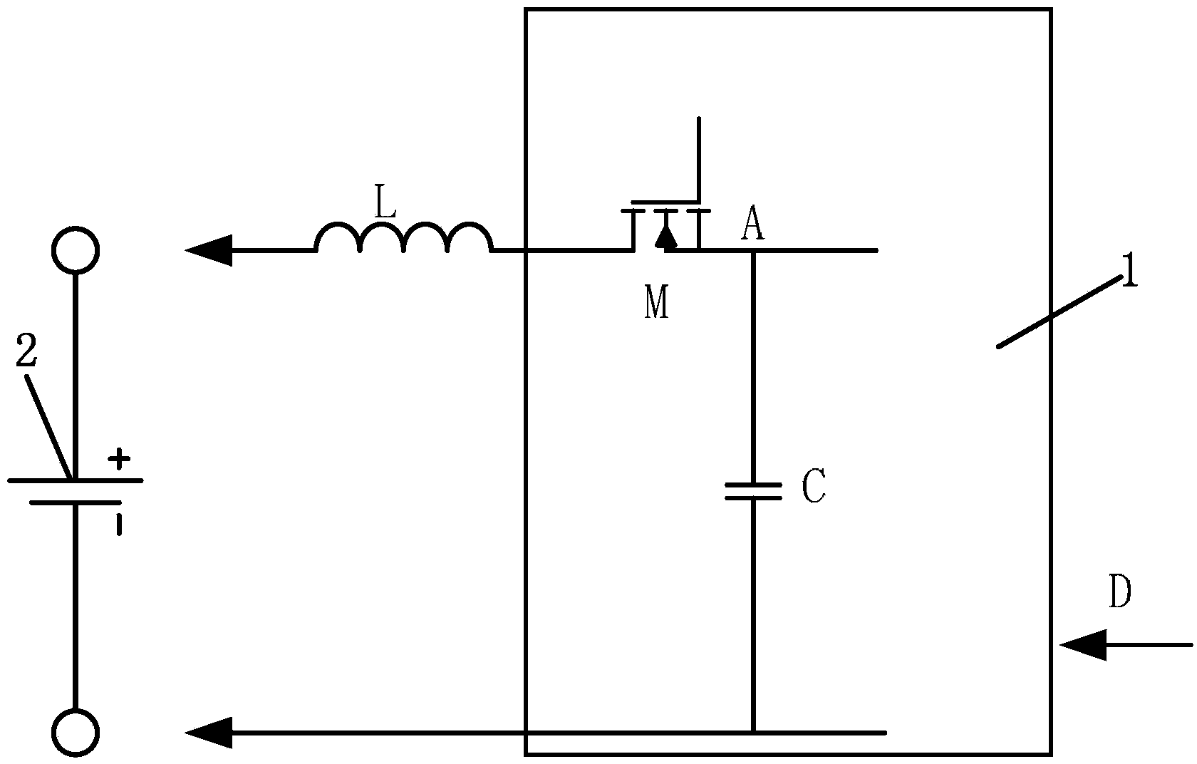
[0029] refer to image 3 , the difference between this embodiment and the first embodiment is that the adjustment module is a power tube M, when the battery module 1 and the battery 2 need to be installed or disassembled, the power tube M is turned into an OFF state, or a high impedance When the battery module 1 is connected to the battery 2 or the battery module 1 needs to start working in the high current mode, the power tube M enters a fully conductive state, or a small impedance state, so that the loop damping state is Little damping.
[0030] In this embodiment, before the battery module 1 is installed or when it needs to be disassembled, the power tube M can be in an OFF state or a high-impedance state, so that the "battery-battery module" loop damping is large enough to ensure that the battery module 1 is connected to the charged battery 2 When , the "battery-battery module" loop does not form a strong oscillation, and the voltage at point A on the input capacitor of t...
Embodiment 3
[0032] refer to Figure 4 The difference between this embodiment and the second embodiment is that the adjustment module includes a power tube M, and a resistor R is connected in parallel between the source and drain of the power tube M. When the battery module 1 and the battery 2 When it needs to be installed or disassembled, turn the power tube M into the OFF state to make the circuit a large damper; when the battery module 1 is connected to the battery 2 or the battery module 1 needs to start working in the high current mode, the power tube M is fully turned on state, making the loop a small damper.
[0033] In this embodiment, before the battery module 1 needs to be installed or disassembled, the power tube M is in the OFF state, and the resistor R connected in parallel between the source and drain terminals of the power tube M ensures that the "battery-battery module" loop damping is large enough to make the battery module 1 contact When the battery is 2, the voltage at ...
PUM
 Abstract
Description
Claims
Application Information
 - R&D
- Intellectual Property
- Life Sciences
- Materials
- Tech Scout
- Unparalleled Data Quality
- Higher Quality Content
- 60% Fewer Hallucinations
Browse by: Latest US Patents, China's latest patents, Technical Efficacy Thesaurus, Application Domain, Technology Topic, Popular Technical Reports.
© 2025 PatSnap. All rights reserved.Legal|Privacy policy|Modern Slavery Act Transparency Statement|Sitemap|About US| Contact US: help@patsnap.com