Trash remover

A cleaning machine and rotating shaft technology, applied in the field of cleaning machines, can solve problems such as difficulty in picking up floating objects, large outward force of dirt, and difficult operation, etc., and achieve the effect of simple structure, low power consumption, and convenient fishing

Inactive Publication Date: 2010-06-16
何光海
View PDF2 Cites 0 Cited by
  • Summary
  • Abstract
  • Description
  • Claims
  • Application Information

AI Technical Summary

Problems solved by technology

Although this structure cleaning machine solves the problem that the rake claws and bottom teeth can effectively insert dirt, its structure is complex, it is difficult to pick up larger floating objects, and it is difficult to operate when there are many and wide floating objects. At this time, the outward force of the dirt is large and the power consumption is high

Method used


Image

  • Trash remover
  • Trash remover
  • Trash remover

Examples


Embodiment 1

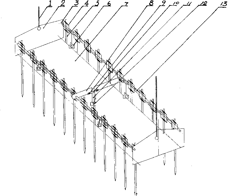
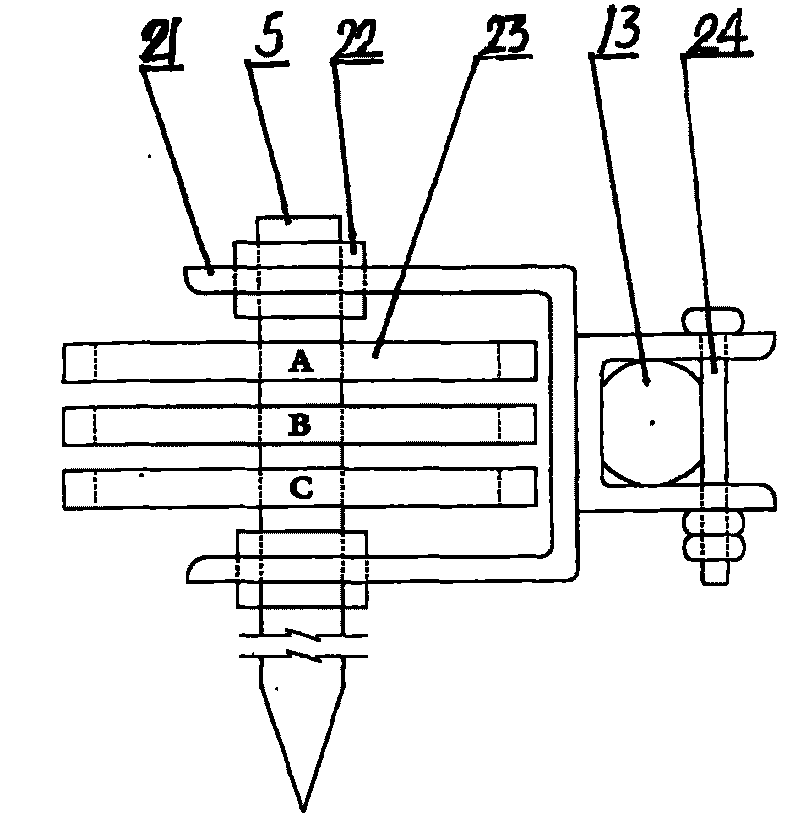
[0014] Example 1, such as figure 1 , 3 As shown, the present invention includes: hoisting equipment, a facility bearing platform 7, an end plate 2, a rotating shaft 13, grid bars 5, power and a rotating device connected to each other by a steel wire rope 1 and a lifting device, and its specific structure is that the bearing platform 7 is composed of two beams It is fixedly connected with the upper bearing plate, the two ends of the beam are connected with the lower parts of the two end plates 2 by bolts or welded, and the upper sides of the two end plates are provided with shaft holes 3 respectively socketed with the ends of the two shafts 13, and the shaft body The upper and lower sides are arc-shaped, the middle part is flat, and the shaft end is circular. The rotating shaft is socketed with the tapered grid bar through the bearing seat on the grid bar hole. The gear 23 and the motor 6 fixed to the rotating shaft are fixedly connected to the grid bar. The gears are connecte...

Embodiment 2

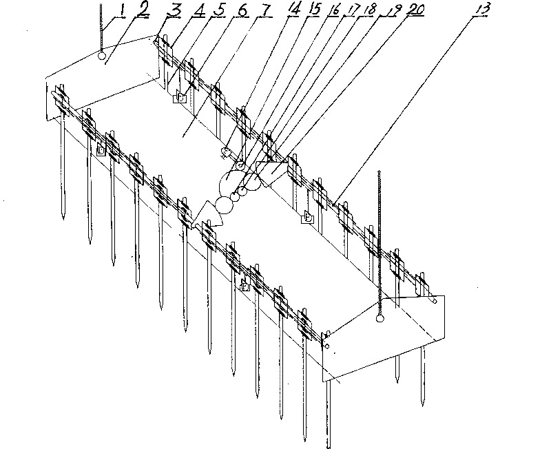
[0015] Example 2, such as figure 2 , 3 As shown, the present invention includes: hoisting equipment, a facility bearing platform 7, an end plate 2, a rotating shaft 13, grid bars 5, power and a rotating device connected to each other by a steel wire rope 1 and a lifting device, and its specific structure is that the bearing platform 7 is composed of two beams It is fixedly connected with the upper bearing plate, the ends of the two beams and the lower parts of the two end plates 2 are connected by bolts or welded, and the upper sides of the two end plates are provided with shaft holes 3 respectively socketed with the ends of the two shafts 13, and the shaft body The upper and lower sides are arc-shaped, the middle part is flat, and the shaft end is circular. The rotating shaft is connected to the tapered grid bar through the grid bar seat 4. The said bar bar seat is two U-shaped with through holes and the backs are fixed. Frame constitutes, and one side U-shaped frame is fix...


PUM


Abstract

The invention discloses a cleaning machine, comprising a lifting device, an equipment plummer (7)connected with the lifting device through a steel wire(1), an end plate(2), rotating shafts (13), a grizzly bar(5) and a drive and transmission device. Two crossbeams and bearing plates thereon are fixedly connected to form the equipment plummer (7). The ends of the crossbeams are fixedly connected with the lower part of the end plate (2). The cleaning machine is characterized in that both sides of the upper end of the end plate(2) are provided with rotating shaft holes(3) which are respectively sleeved with the two rotating shafts; the rotating shafts are sleeved with the tapered grizzly bar(5) through a bearing seat(22); a gear wheel(23) connected with the gear wheel of a motor(6) is arrangedon the grizzly bar(5); and the middle parts of the two rotating shafts (13) are connected with a synchronous revolving member. The cleaning machine has no need to stop the motor at the time of salvage and is convenient to salvage large and thick flotage stacks and is high in work efficiency, low in power consumption, simple in structure and convenient in operation.

Description

technical field [0001] The invention relates to a device for cleaning dirt at the trash rack of a hydropower station, in particular to a dirt cleaning machine which can effectively remove various floating objects in water. Background technique [0002] Trash racks are installed at the water inlets of hydroelectric power stations to intercept debris in the water to ensure the safe operation of the generating units. The floating objects at the trash rack need to be removed regularly to ensure smooth flow of water. Currently, there are mainly two types of cleaning machines used to clean up the dirt in front of the trash rack of hydropower stations. When the tooth rake moves upwards to drive the dirt to the top rotation position, the dirt falls down by its own weight. For example, Chinese patent 200320107176.4 basically belongs to this structure. When cleaning the dirt with this structure, it is often necessary to stop the generator and then salvage it. When there are many and ...

Claims


Application Information

Patent Timeline
Patent Type & Authority Patents(China)
IPC IPC(8): E02B15/10
Inventor 何光海
Owner 何光海
Why Eureka
Try Eureka