Eureka AIR delivers breakthrough ideas for toughest innovation challenges, trusted by R&D personnel around the world.

FPGA (Field Programmable Gate Array) based multi-channel data transmission synchronization delay measurement method and system

A technology of data transmission and time delay, which is used in electrical digital data processing, instruments, etc.

Inactive Publication Date: 2014-10-01
XIDIAN UNIV
View PDF3 Cites 12 Cited by
  • Summary
  • Abstract
  • Description
  • Claims
  • Application Information

AI Technical Summary

Problems solved by technology

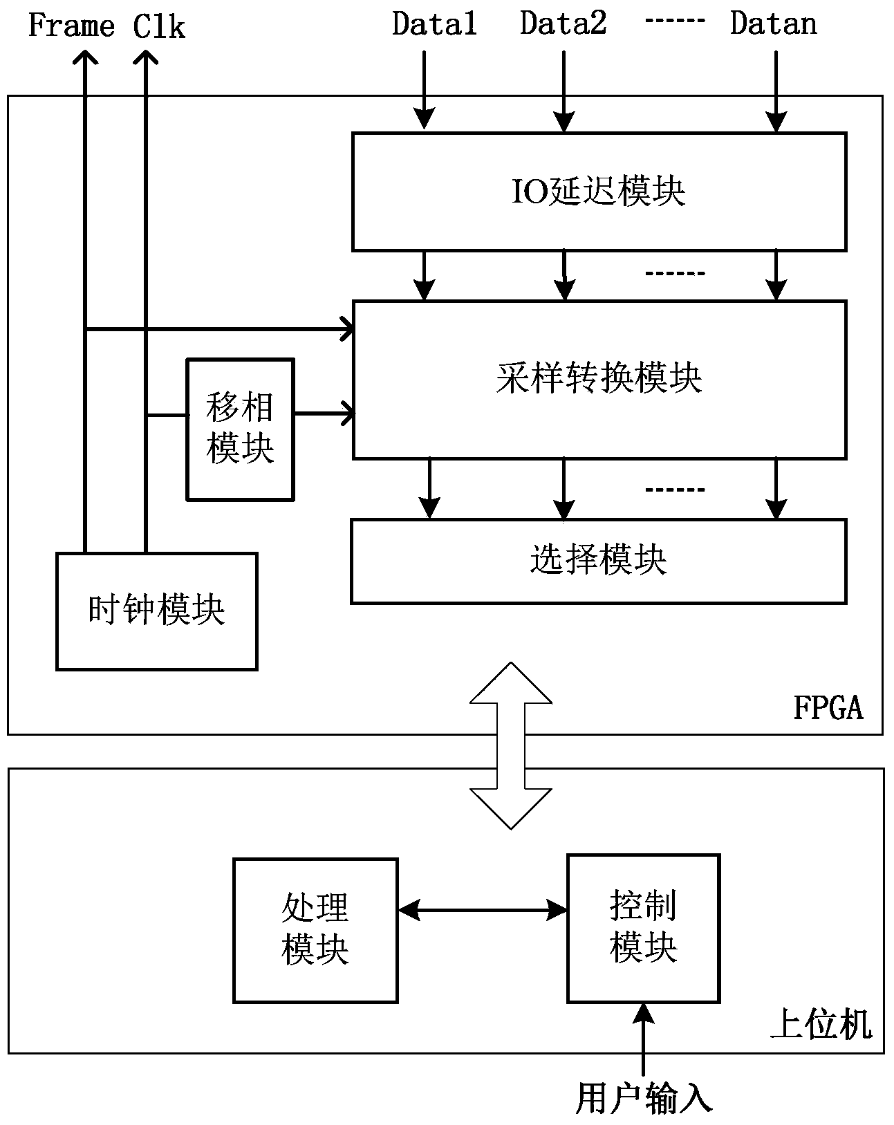
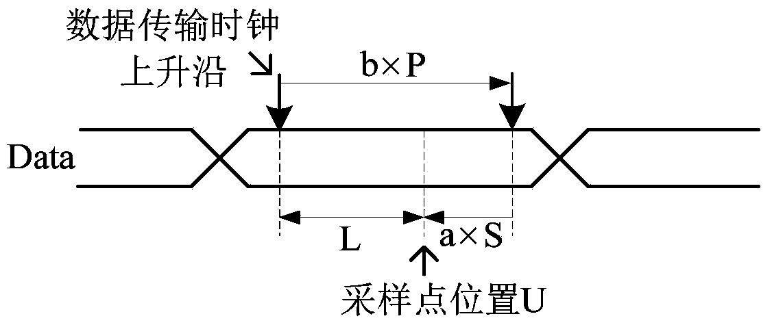
[0004] Aiming at the problem that the measurement of synchronous time delay cannot be realized in the prior art, the present invention provides a method for measuring the synchronous time delay of multi-channel data transmission based on FPGA, and the present invention realizes the movement of the sampling point position by shifting the serial data to the left , by moving the sampling clock to the right to expand the moving range of the sampling point position, it has the advantages of high resolution, wide range, multi-channel automatic measurement and strong anti-interference

Method used


Image

  • FPGA (Field Programmable Gate Array) based multi-channel data transmission synchronization delay measurement method and system
  • FPGA (Field Programmable Gate Array) based multi-channel data transmission synchronization delay measurement method and system
  • FPGA (Field Programmable Gate Array) based multi-channel data transmission synchronization delay measurement method and system

Examples


Embodiment Construction

[0073] refer to figure 1 , illustrate the method for measuring the multi-channel data transmission synchronous time delay based on FPGA of the present invention, be applied to Field Programmable Gate Array FPGA and upper computer; FPGA comprises clock module, IO delay module, phase-shift module, sampling conversion module and selection module ; The upper computer includes a processing module and a control module, including the following steps:

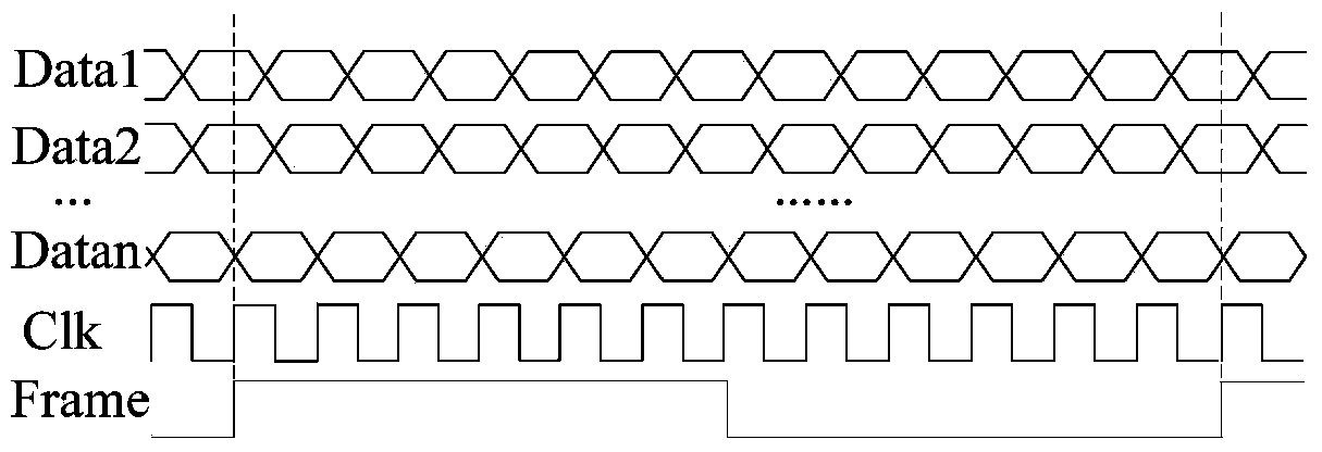
[0074] Step 1, such as figure 2 As shown, the clock module generates the data transmission clock Clk and the frame synchronization signal Frame, and sends the data transmission clock Clk to the phase shifting module, and sends the frame synchronization signal Frame to the sampling conversion module;

[0075] Step 2, the control module receives the data link label input by the user, the frequency f of the serial data corresponding to the link label, and the signal-to-noise ratio z of the serial data corresponding to the link label; th...


PUM


Abstract

The invention discloses a FPGA (Field Programmable Gate Array) based multi-channel data transmission synchronization delay measurement method and system and relates to the electronic measurement technical field. The FPGA based multi-channel data transmission synchronization delay measurement method comprises step 1, providing a data transmission clock and a frame synchronization signal through a clock module; step 2, sending the every time of amount of phase shift of the clock to a phase shifting module, obtaining the maximum time of phase shift and setting the times of phase shift of the clock; step 3, sending delay data to a sampling conversion module through an IO (Input and Output) delay module; step 4, sending a sampling clock to the sampling conversion module through the phase shifting module; step 5, sending sampling data which are corresponding to link labels to a processing module through the sampling conversion module; step 6, determining whether the position of a sampling point is an unstable transmission position or not through the processing module; step 7, setting the delay order of the data to increase 1 through a control module; step 8, obtaining the unstable transmission position through the processing module; step 9, determining the synchronization delay of the sampling data which are corresponding to the link labels through the processing module. The FPGA based multi-channel data transmission synchronization delay measurement method and system is used for implementing the measurement on the data synchronization delay.

Description

technical field [0001] The invention relates to the technical field of electronic measurement, in particular to a measurement method and system for synchronous time delay of multi-channel data transmission based on FPGA. Background technique [0002] With the increasing maturity of information technology and electronic technology, the gradual improvement of information acquisition technology, the improvement of the performance of acquisition equipment, the gradual popularization of high-sampling rate and high-precision front-end applications, a large amount of high-speed data has emerged. Serial data transmission technology has the advantages of fast transmission speed and strong anti-interference ability, which satisfies the transmission requirements of high speed and high reliability, and is widely used in many fields such as modern science, industrial production and national defense construction. [0003] The serial transmission technology used in the prior art mainly has...

Claims


Application Information

Patent Timeline
IPC IPC(8): G06F13/38
Inventor 苏涛逄锦昊陈建康秦岩田充足熊梓成
Owner XIDIAN UNIV
Why Eureka
Eureka Blog
Learn More