Split control valve of common rail oil injector
A common rail fuel injector, split technology, applied in the direction of machine/engine, fuel injection device, engine components, etc., can solve the problems of high cost, high processing requirements, low qualification rate, etc., to improve the difficulty and reduce production costs. , to ensure the effect of operability
- Summary
- Abstract
- Description
- Claims
- Application Information
AI Technical Summary
Problems solved by technology
Method used
Image
Examples
Embodiment 1
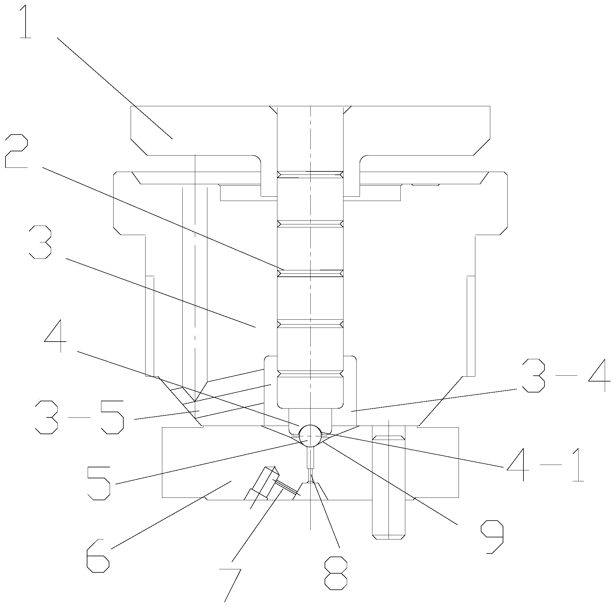
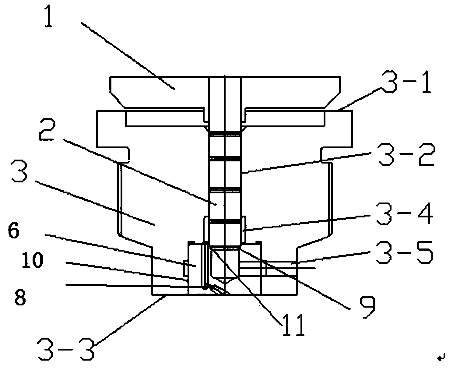
[0024] Such as figure 2 Shown: the central axis of the guide hole 3-2 and the oil tank 3-4 coincides with the central axis of the overall structure formed by the valve seat 6 and the valve body 3, and the guide hole 3-2 and the oil tank 3-4 are arranged on the valve body. In the body 3, the beginning of the guide hole 3-2 is located on the upper surface of the valve body 3, the end of the oil tank 3-4 is flush with the upper surface of the groove 10, and the end of the guide hole 3-2 extends into the valve seat 6 and extends to the valve seat 6 The diameter of a section of guide hole 3-2 in the valve body 3 is smaller than the diameter of the guide hole 3-2 in the valve body 3, and the guide hole 3-2 in the valve seat 6 and the lower end surface of the oil tank 3-4 pass through the funnel-shaped conical surface 9. , the upper end surface of the conical surface 9 is flush with the upper end surface of the valve seat 6, and the outer circumference of the control rod is provided...
Embodiment 2
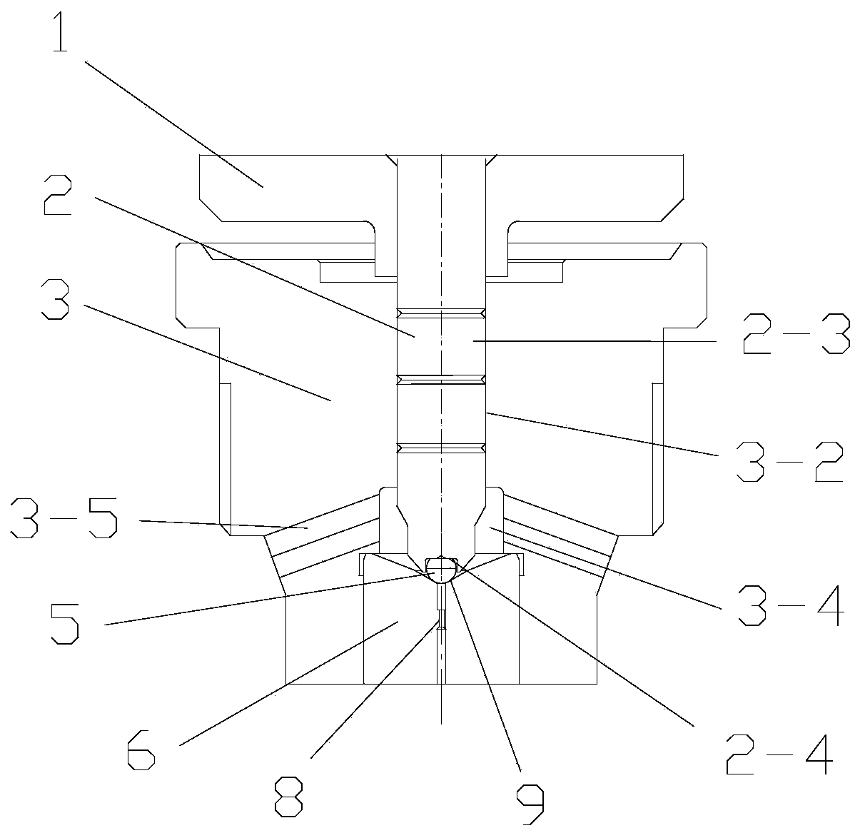
[0029] Such as image 3 Shown: the central axis of the guide hole 3-2, the oil tank 3-4, the oil outlet orifice 8 coincides with the central axis of the integral structure formed by the valve seat 6 and the valve body 3, the guide hole 3-2 and the oil tank 3-4 is set on the valve body 3, the beginning of the guide hole 3-2 is located on the upper end surface of the valve body 3, the end of the oil storage groove 3-4 is flush with the upper end surface of the groove 10, and the oil outlet orifice 8 is set in the valve seat 6 , and the oil outlet orifice 8 and the oil tank 3-4 pass through the funnel-shaped conical surface, and the upper edge of the funnel-shaped conical surface is flush with the upper end surface of the valve seat 6; the oil drain hole 3 The beginning of -5 is located on the outer wall of the valve body 3, and the end of the oil drain hole 3-5 is located on the side wall of the oil tank 3-4;
[0030] The lower end surface of the control rod 2 is provided with ...
PUM
 Abstract
Description
Claims
Application Information
 - R&D
- Intellectual Property
- Life Sciences
- Materials
- Tech Scout
- Unparalleled Data Quality
- Higher Quality Content
- 60% Fewer Hallucinations
Browse by: Latest US Patents, China's latest patents, Technical Efficacy Thesaurus, Application Domain, Technology Topic, Popular Technical Reports.
© 2025 PatSnap. All rights reserved.Legal|Privacy policy|Modern Slavery Act Transparency Statement|Sitemap|About US| Contact US: help@patsnap.com


