Plastic oil cup device for hydraulic braking device

A technology of hydraulic brakes and brakes, which is applied to the field of oil cup devices on hydraulic brakes and plastic oil cup devices, which can solve the problems of scrapped brakes, difficult forming and processing, and high production costs of oil cups, so as to reduce difficulty and reduce materials. cost, avoiding irreparable effects

Active Publication Date: 2014-10-01
RUIAN JINJI VEHICLE PARTS COMPONENTS
View PDF6 Cites 8 Cited by
  • Summary
  • Abstract
  • Description
  • Claims
  • Application Information

AI Technical Summary

Problems solved by technology

[0003] The oil cup device of the existing structure is mainly cast and formed of metal material, and the main body of the oil cup and the main brake pump body are integrally cast and processed; it has the following defects: 1) The main body of the oil cup and the main brake pump are integrally cast and formed, and the molding process Difficulty, inconvenient processing and manufacturing; 2) The oil cup is a metal casting, which has high material cost, resulting in high production cost of the oil cup; 3) The main body of the oil cup and the main brake pump are integrally cast, and when the oil cup is cracked and damaged , can not be repaired twice, resulting in the scrapping of the entire brake brake, resulting in a waste of resources

Method used


Image

  • Plastic oil cup device for hydraulic braking device
  • Plastic oil cup device for hydraulic braking device
  • Plastic oil cup device for hydraulic braking device

Examples


Embodiment Construction

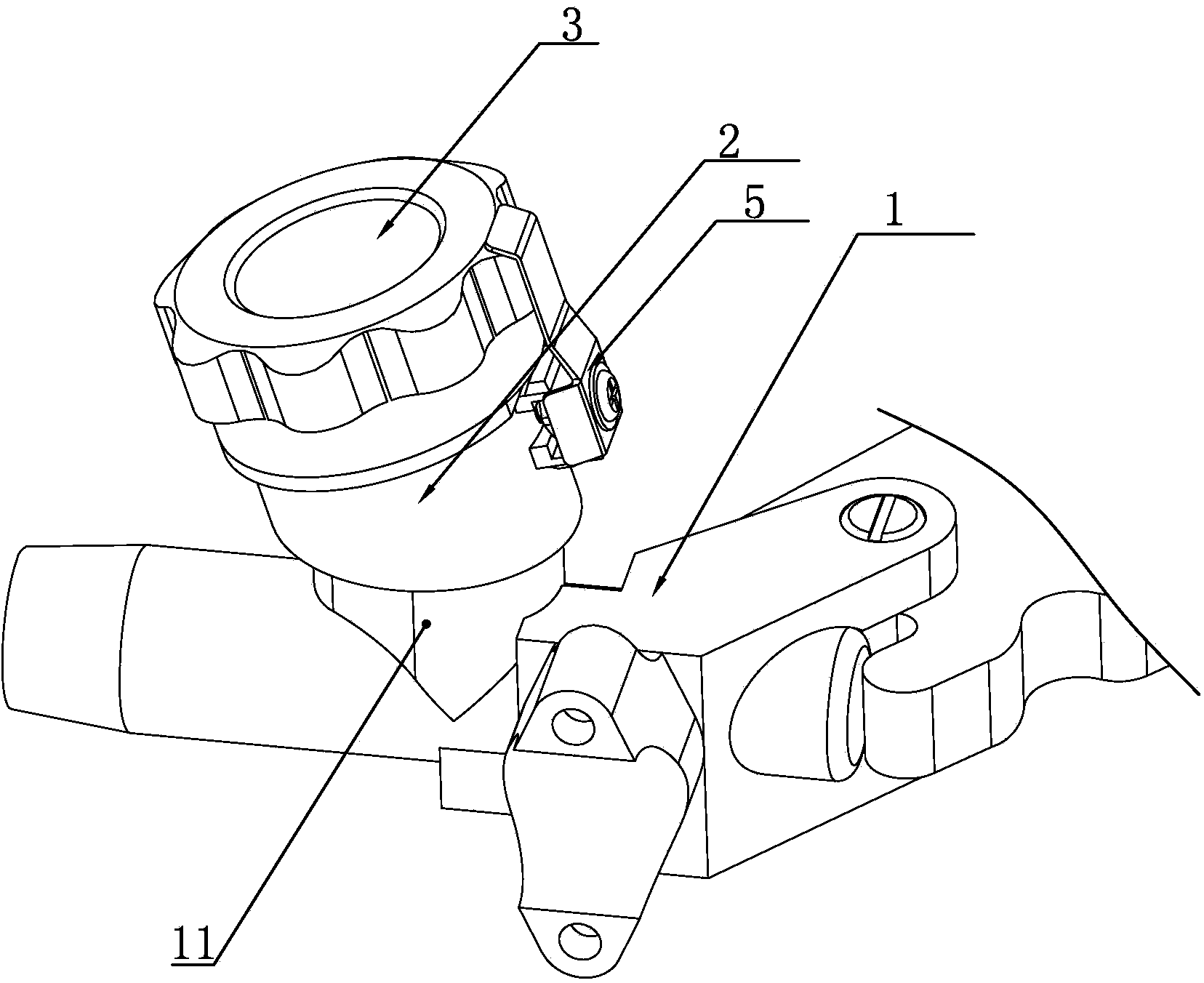
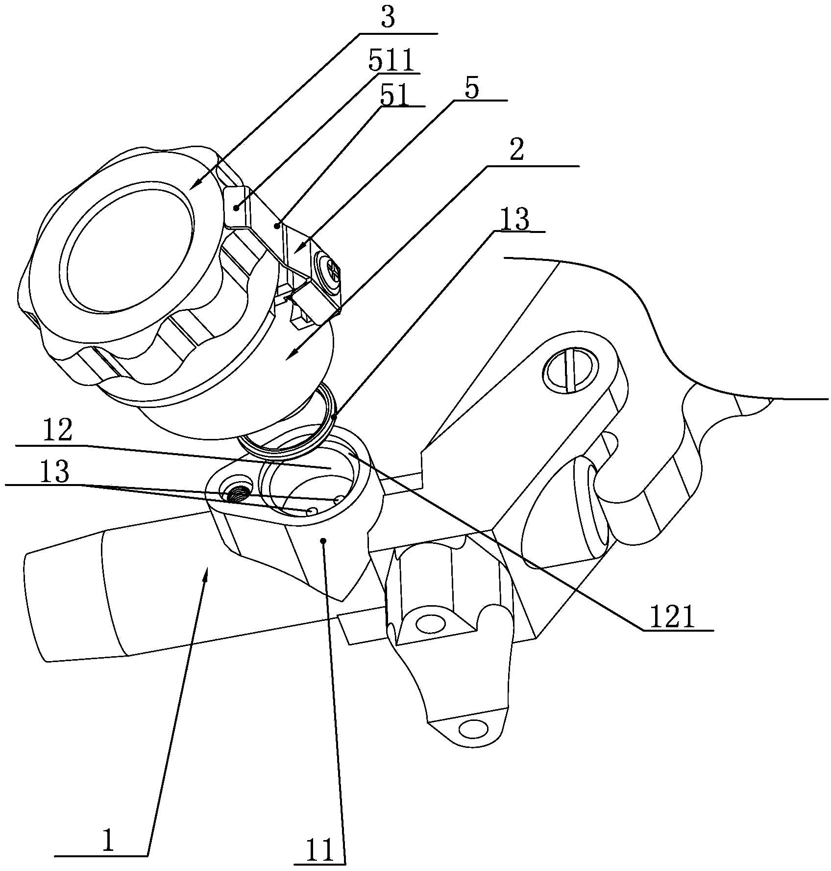
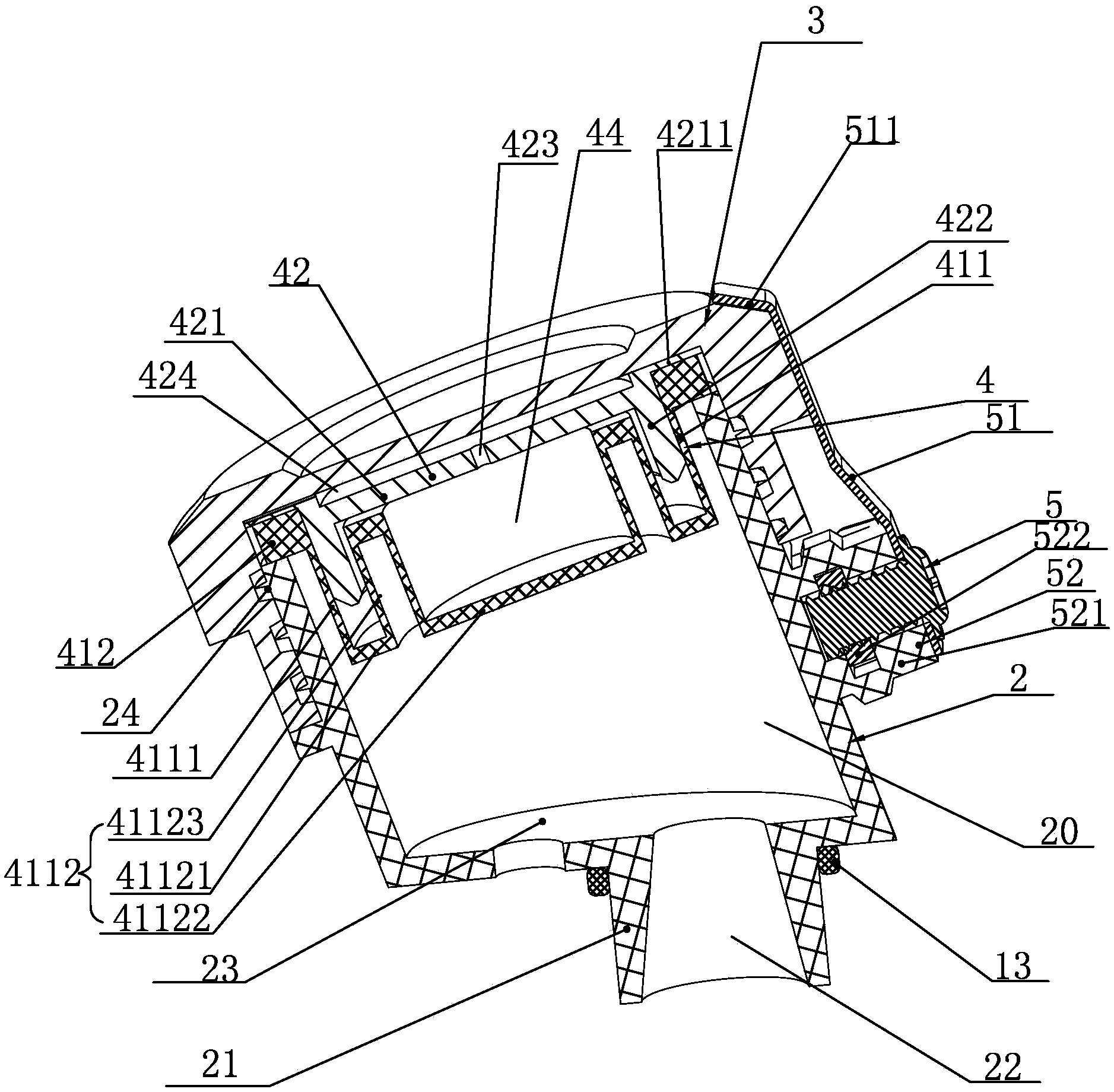
[0029] See attached figure 1 to attach Figure 5 , a plastic oil cup device for a hydraulic brake disclosed in the present invention includes a brake main pump body 1, an oil cup main body 2 with an oil storage chamber 20, and an oil storage chamber 20 covered on the oil cup main body 2 An oil cup cover 3 at the mouth, an oil cup pad 4 is arranged between the oil cup cover 3 and the mouth of the oil storage chamber 20 on the oil cup main body 2 . The main body 2 of the oil cup is a plastic part formed by plastic injection molding. The bottom of the main body 2 of the oil cup extends downward with a positioning post 21, and the positioning post 21 is provided with an oil passage 22 communicating with the oil storage chamber 20; The main pump body 1 is provided with an oil cup base 11 installed on the main body 2 of the oil supply cup. The oil cup base 11 is provided with a positioning seat hole 12, and the bottom of the positioning seat hole is provided with an oil inlet and ...


PUM


Abstract

The invention relates to a plastic oil cup device for a hydraulic braking device. The plastic oil cup device comprises a main braking pump body, an oil cup main body with an oil storing cavity, and an oil cup cap which covers the opening of the oil storing cavity in the oil cup main body, wherein an oil cup washer is arranged between the oil cup cap and the opening of the oil storing cavity in the oil cup main body; the oil cup main body is a plastic part which is injected with plastic, and the bottom of the oil cup main body extends downwards to form a positioning column; an oil communicating channel communicated with the oil storing cavity is formed in the positioning column; an oil cup substrate on which the oil cup main body is mounted is arranged on the main braking pump body, and a positioning seat hole is formed in the oil cup substrate; an oil inlet and an oil outlet which are communicated with a plunger valve component are formed in the bottom of the positioning seat hole; the positioning column at the bottom of the oil cup main body is inserted into the positioning seat hole in the oil cup substrate in a sealing manner, and the bottom of the oil cup main body is supported on the oil cup substrate; and the oil cup main body is removably mounted on the oil cup substrate. Compared with the prior art, the plastic oil cup device has the advantages of convenient processing, low cost, convenient maintenance and replacement, convenient assembling and good sealing performance.

Description

technical field [0001] The invention relates to handle hydraulic brakes for motorcycles, power-assisted vehicles, etc., specifically an oil cup device on a hydraulic brake, specifically a plastic oil cup device for a hydraulic brake. Background technique [0002] The front brake operation of motorcycles, mopeds, etc. is generally arranged on the handle, which is called the handle brake; the existing handle brake usually adopts a hydraulic pump to replace the traditional cable structure. Existing hydraulic brakes usually include a brake main pump body, an oil cup device is arranged on the brake main pump body, and a plunger valve assembly for controlling the brake oil in the oil cup device; the oil cup device includes a The main body of the oil cup in the chamber, the main body of the oil cup and the brake main pump body are integrally cast, the mouth of the main body of the oil cup is covered with an oil cup cover, and the mouth of the oil cup and the main body of the oil cu...

Claims


Application Information

Patent Timeline
Patent Type & Authority Applications(China)
IPC IPC(8): B60T11/16B60T17/06
Inventor 侯志坚侯智慧侯兴柱
Owner RUIAN JINJI VEHICLE PARTS COMPONENTS
Why Eureka
Try Eureka