
Series load control apparatus and marker light apparatus

A technology for load control and sign light, which is applied to lighting devices, circuit devices, and loss prevention measures for lighting devices, etc., can solve the problems that the function of the sign light cannot be realized, the light source is not bright, and the power supply of the lighting control mechanism cannot be ensured, and the improvement is achieved. Effect of Anomaly Detection Accuracy

Inactive Publication Date: 2014-09-24
TOSHIBA LIGHTING & TECH CORP
View PDF1 Cites 2 Cited by
  • Summary
  • Abstract
  • Description
  • Claims
  • Application Information

AI Technical Summary

Problems solved by technology

[0012] However, in Patent Document 1, since the output side of the insulating type transformer is forcibly opened, the power supply for the lighting control mechanism, the solid-state light-emitting element, etc. cannot be ensured after the opening.
Therefore, when the output side of the insulating type transformer is temporarily opened due to malfunction of the detection mechanism for detecting abnormality or the determination mechanism for determining the presence or absence of abnormality, or other reasons, the light source may remain unlit, and the function as a marker light cannot be realized. bad situation
Not only is it difficult to carry out the fixed work including the marker light in manual repair, but also it is futile to carry out the work every time due to malfunction, and it is expected that the repair can be carried out automatically
However, installing a special automatic recovery mechanism such as remote control will lead to a significant cost increase

Method used


Image

  • Series load control apparatus and marker light apparatus
  • Series load control apparatus and marker light apparatus
  • Series load control apparatus and marker light apparatus

Examples


Embodiment Construction

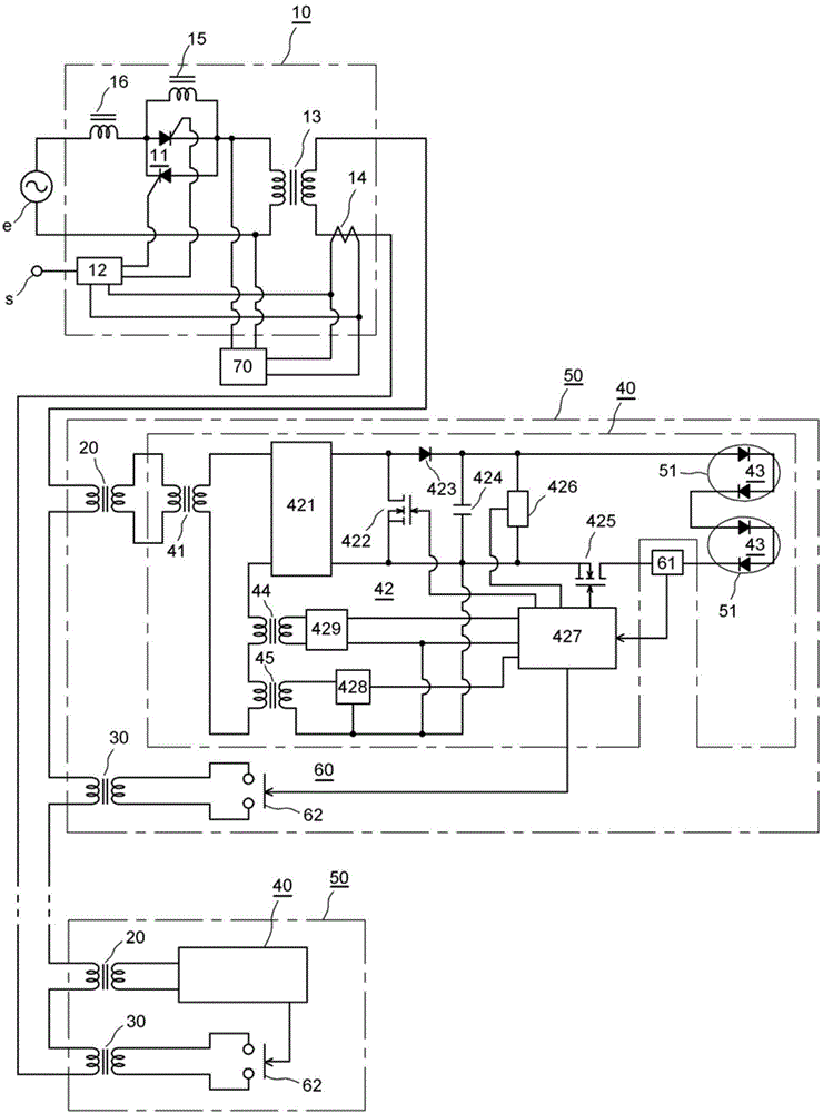
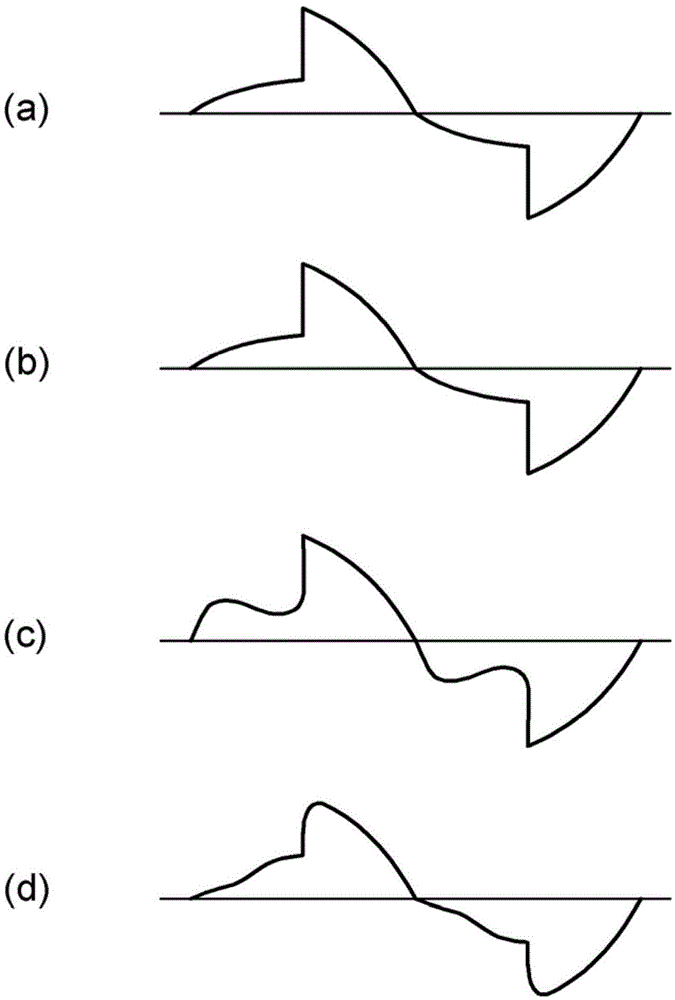
[0028] Below, refer to figure 1 and figure 2 One embodiment of the present invention will be described. figure 1 It is a circuit diagram showing an embodiment of the DC load control device and the indicator light device of the present invention, figure 2 It is a waveform diagram illustrating the function.

[0029] 10 is a constant current power supply device, and a plurality of first saturable mechanisms 20 are connected in series on the output side of the constant current power supply device 10 . In addition, second saturable mechanisms 30 are connected in series corresponding to the first saturable mechanisms 20 . In this embodiment, the second saturable mechanism 30 has a larger capacity than the first saturable mechanism 20 . The first and second saturable means 20 and 30 are, for example, insulating transformers, but may also be non-insulating transformers, semiconductor devices configured to conduct when a voltage equal to or greater than a predetermined voltage is...


PUM


Abstract

The invention provides a series load control apparatus and a marker light apparatus capable of detecting abnormal states of loads including a lighting control unit, a solid light-emitting element etc., and continuously supplying power for the loads in the condition of malfunctions of an abnormality detecting unit of the loads. The abnormality detecting unit opens an open-closed unit (62) in a condition of malfunction due to a certain reason, and opens an output section of a second saturable unit (30). In the condition, the second saturable unit (30) repeats non-saturated-saturated states in each half cycle of an alternating current voltage, but since a first saturable unit (20) is unsaturated and supplies power for the loads (10) as usual,the lighting control unit (42) performs lighting control of light sources (43, 43) according to output current signals of a constant current power supply device (10).

Description

technical field [0001] The present invention relates to a series load control device and a marker lamp device for supplying power to a plurality of loads provided in series with each other in a constant current power supply device. Background technique [0002] For example, a plurality of buried or above-ground marker lights for runways and guiding roads of an airport are connected in series, and are powered by an AC constant current power supply device for lighting. Since it is necessary to change the light output of the marker lamp according to the surrounding environment, dimming lighting can be performed by changing the output current value of the constant current power supply device. [0003] In addition, each marker lamp supplies power to a light bulb as a light source from the constant current power supply device via a saturable mechanism such as a saturable insulating transformer. When the saturable mechanism is a saturable insulating transformer, the input windings...

Claims


Application Information

Patent Timeline
Patent Type & Authority Applications(China)
IPC IPC(8): H05B37/02H05B37/04H05B44/00
CPCH05B33/0818H05B37/038H05B33/0815H05B33/0884Y10T307/445H02J4/00F21V15/01H05B45/50H05B47/235H05B45/382
Inventor 新野真吾松野将
Owner TOSHIBA LIGHTING & TECH CORP
Learn More