High-mixing-ratio ignition tank

A high mixing ratio, ignition tank technology, applied in the field of boiler soot blowing, can solve the problems of insufficient deflagration, carbon accumulation and water blockage, weak soot blowing effect, etc., and achieve the effect of improving the mixing adequacy.

Inactive Publication Date: 2014-09-24
BEIJING GUANGHUA TEXTILE GRP +1
View PDF7 Cites 8 Cited by
  • Summary
  • Abstract
  • Description
  • Claims
  • Application Information

AI Technical Summary

Problems solved by technology

[0003] In order to solve the problems of insufficient deflagration, weak soot blowing effect, and blockage of pipelines caused by insufficient mixing of the existing mixing ignition tank, the present invention provides a high mixing ratio ignition tank, including an air inlet connection pipe, a gas chamber Chamber, mixing chamber, ignition chamber and flame outlet pipe; the gas chamber, mixing chamber and ignition chamber are sequentially arranged inside the ignition tank according to the direction of air intake; the air inlet pipe is connected to the gas chamber chamber and mixing chamber; a secondary mixed gas splitter plate is set between the mixing chamber and the ignition chamber to separate the mixing chamber and the ignition chamber; the middle part of the air inlet connection is provided with a gas mixing inclined hole The tail of the air inlet connecting pipe is provided with a primary mixed gas outlet oblique hole; the secondary mixed gas splitter plate is evenly provided with a plurality of first through holes perpendicular to the plane where the secondary mixed gas splitter plate is located and the second through hole in an inclined shape; the flame outlet pipe communicates with the ignition chamber

Method used


Image

  • High-mixing-ratio ignition tank
  • High-mixing-ratio ignition tank
  • High-mixing-ratio ignition tank

Examples


Embodiment Construction

[0016] The technical solutions of the present invention will be further described below in conjunction with the accompanying drawings and embodiments.

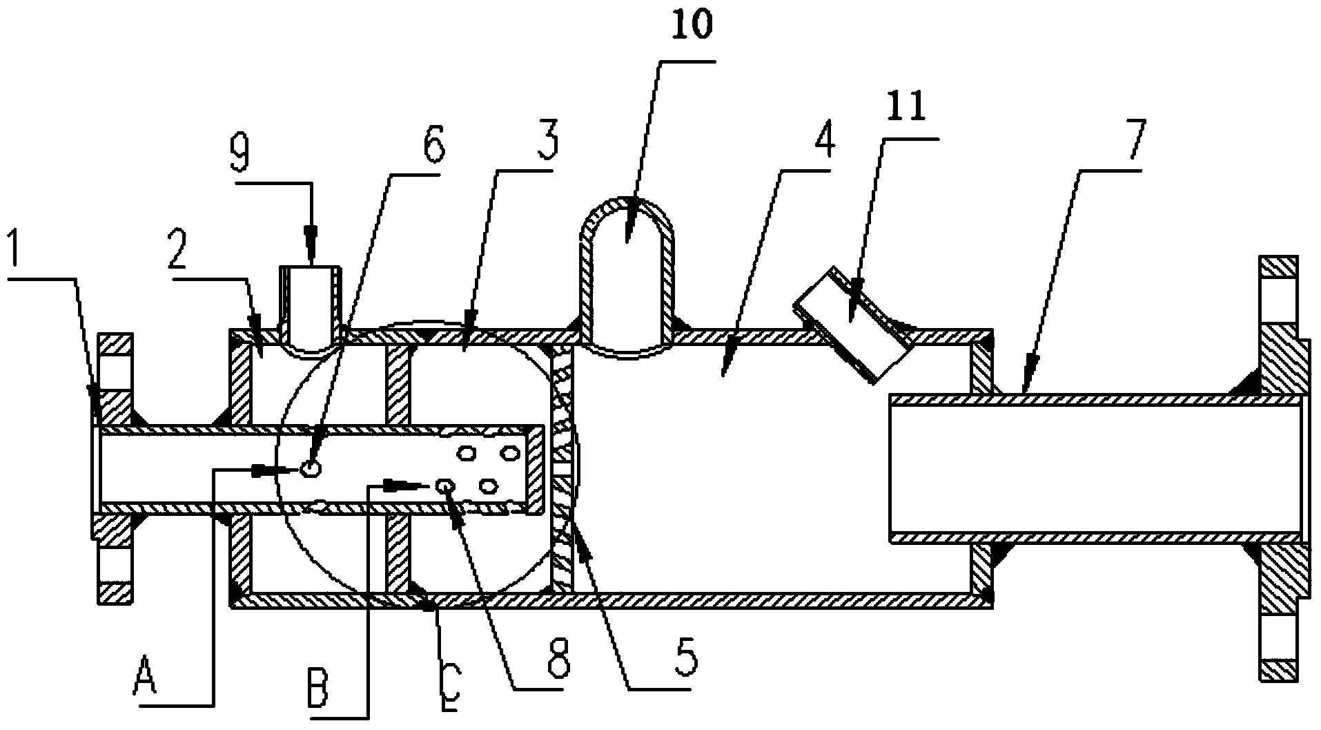
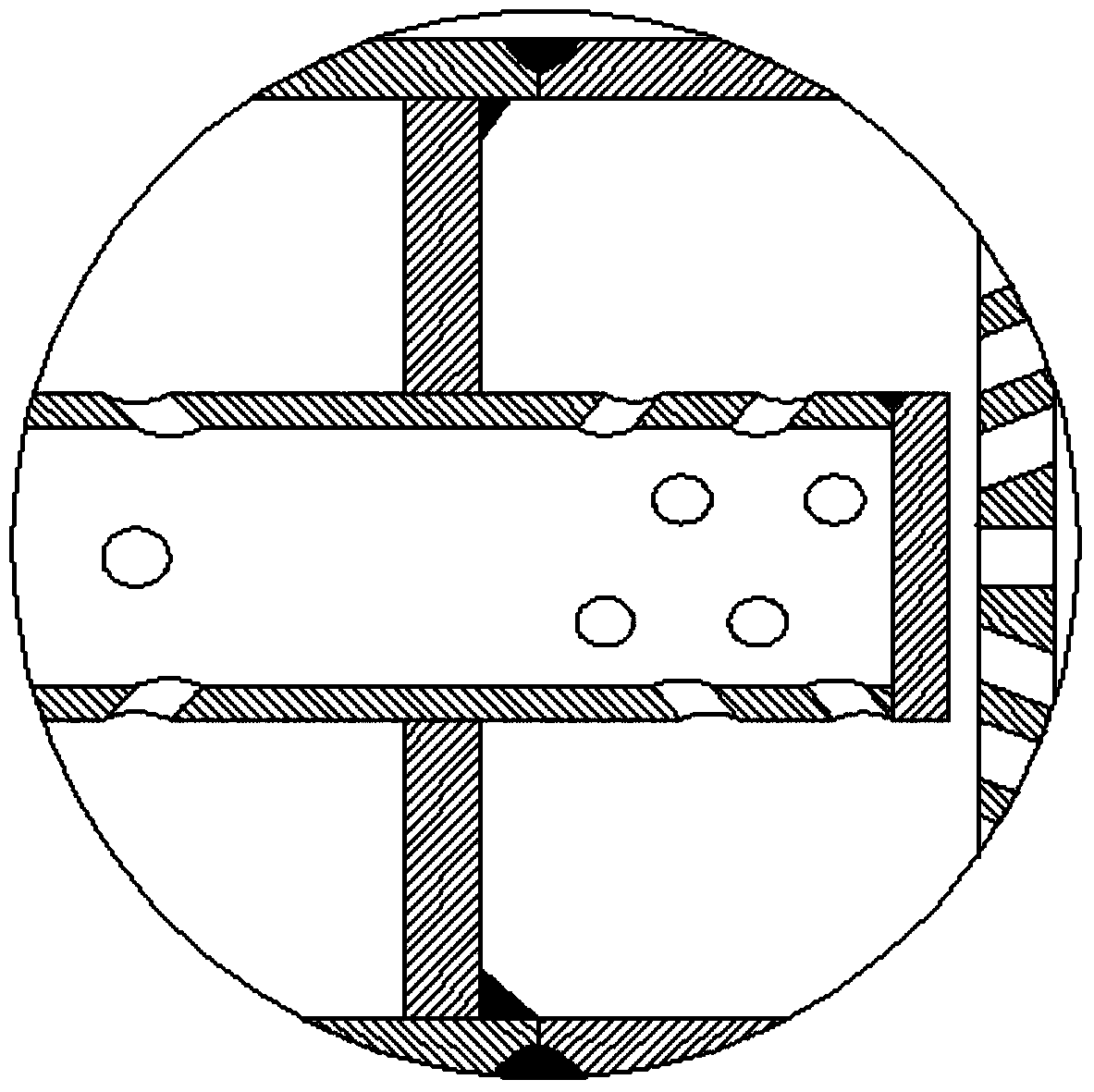
[0017] see figure 1 , the embodiment of the present invention provides a high mixing ratio ignition tank for the mixing and detonation of gas and air, the air inlet connecting pipe 1, the gas chamber 2, the mixing chamber 3, the ignition chamber 4 and the flame outlet pipe 7. Among them, the gas chamber 2, the mixing chamber 3 and the ignition chamber 4 are sequentially arranged inside the ignition tank according to the air intake direction; the air inlet connecting pipe 1 communicates with the gas chamber 2 and the mixing chamber 3; the mixing chamber 3 and the ignition chamber 4 is provided with a secondary mixed gas splitter plate 5, and the secondary mixed gas splitter plate 5 separates the mixing chamber 3 from the ignition chamber 4; the middle part of the air inlet connecting pipe 1 is provided with a gas mixing incline...


PUM


Abstract

The invention discloses a high-mixing-ratio ignition tank, and belongs to the technical field of boiler soot blowing. The ignition tank comprises an air inlet connecting pipe, a gas chamber, a mixing chamber, an ignition chamber and a flame outlet pipe, wherein the gas chamber, the mixing chamber and the ignition chamber are arranged in the ignition tank in sequence according to a gas inlet direction; the air inlet connecting pipe is communicated with the gas chamber and the mixing chamber; a secondary mixed gas shunt plate is arranged between the mixing chamber and the ignition chamber; a gas mixing inclined hole is formed in the middle part of the air inlet connecting pipe; primary mixed gas outlet inclined holes are formed in the tail part of the air inlet connecting pipe; a plurality of vertical first through holes and inclined second through holes are uniformly formed in the secondary mixed gas shunt plate; the flame outlet pipe is communicated with the ignition chamber. According to the high-mixing-ratio ignition tank, mixed gas can uniformly enter the ignition chamber by improving the structure of the air inlet connecting pipe and arranging the shunt plate between the mixing chamber and the ignition chamber, so that the mixing full degree of air and gas is greatly improved.

Description

technical field [0001] The invention relates to the technical field of boiler soot blowing, in particular to an ignition tank with a high mixing ratio. Background technique [0002] The soot blower is an indispensable and important auxiliary equipment for various waste heat boilers and utility boilers. It plays a vital role in improving the heat exchange efficiency of each heating surface of the boiler, that is, increasing the output of the boiler. The hybrid ignition tank is one of the most important components on the shock wave generation system. Gas and air are mixed in the ignition tank, and then transported to the shock wave generator tank through the outlet pipeline. The uniformity of gas mixing in the ignition tank directly affects the soot blowing effect. The existing hybrid ignition tank only realizes simple mixing through gas and air direct flow and confluence when gas and air are mixed, which leads to insufficient mixing of gas and air, which directly affects the...

Claims


Application Information

Patent Timeline
Patent Type & Authority Applications(China)
IPC IPC(8): F23D14/02F23D14/70F23J1/00F23J3/00
Inventor 廖志超张博张明红刘康钟声赵勇
Owner BEIJING GUANGHUA TEXTILE GRP
Why Eureka
Try Eureka