Cap-screwing machine chuck

The technology of capping machine and claw head is applied in the field of capping machine claw head, which can solve the problems of insufficient equipment optimization, complicated mechanism design, complicated design, etc., and achieve the effects of excellent overall machine, simplified design and reduced cost.

Active Publication Date: 2014-09-24
CHANGZHOU HUITUO TECH
View PDF12 Cites 5 Cited by
  • Summary
  • Abstract
  • Description
  • Claims
  • Application Information

AI Technical Summary

Problems solved by technology

[0002] The automatic capping machine is a device that can screw the cap on the bottle body. It is widely used in daily chemical, food, medicine and other industries. Its structure generally includes a frame, a power transmission device and a capping assembly. There is a rotating part in the cap assembly, and the power device drives the rotating part to rotate. The bottle cap is stuck in the chuck of the rotating part. With the rotation of the rotating part, the bottle cap is tightened on the bottle body. It is a claw structure. For example, application number 201210474244.4 discloses a capping device on a capping machine. The capping device uses a push rod to push the claws to achieve opening and tightening. Although it can also grasp the bottle cap, However, its mechanism design is relatively complicated; application number 201310114217.0 discloses a directional capping device for the diversion tank cover, which also pushes the end of the claw to make it open or tighten; in addition to the claw head of the above-mentioned claw structure, there is also There is a mechanism that adopts four-wheel positioning, clamping and rotating, such as the product that the applicant applied for before, application number 201420035848.3 discloses a fully automatic multi-functional capping machine, and the four-wheel capping method is disclosed in Figure 8 of this application , this method is currently more common, and the rotation effect is better, but its design is also more complicated, and there are deficiencies in equipment optimization

Method used


Image

  • Cap-screwing machine chuck
  • Cap-screwing machine chuck
  • Cap-screwing machine chuck

Examples


Embodiment 1

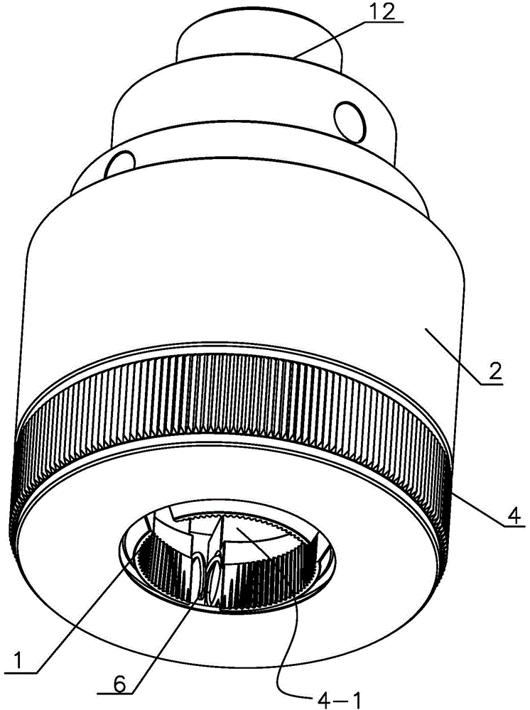
[0032] Such as Figure 4 , the claw seat 2 has an inner cavity, the bottom of the claw seat 2 is equipped with a claw cover seat 4, the center of the claw cover seat 4 has a bottle cap inlet 4-1, and several claws 1 evenly surround the inner cavity of the claw seat 2 and are placed on the claw cover seat 4 on;

[0033] Such as figure 2 image 3 , the pusher 3 includes a piston 5, the outer ring of the piston 5 is in sealing and sliding contact with the inner cavity of the claw seat 2, the bottom surface of the piston 5 is provided with the same number of wedges 5-1 as the number of claws 1, and each claw 1 is provided with a chute 1 -1, the wedge 5-1 on the bottom surface of the piston 5 is correspondingly inserted into the chute 5-1;

[0034] The inclination direction of the wedge 5-1 and the chute 1-1 is upwardly inclined from the outside to the inside, and the surrounding claws 1 are connected with the claws 1 by a compression spring 6 .

[0035]It also has a pin 7 and...

Embodiment 2

[0037] Such as Figure 5 , the claw seat 2 has an inner cavity, the bottom of the claw seat 2 is equipped with a claw cover seat 4, the center of the claw cover seat 4 has a bottle cap inlet 4-1, and several claws 1 evenly surround the inner cavity of the claw seat 2 and are placed on the claw cover seat 4 on;

[0038] Such as figure 2 image 3 , the pusher 3 includes a piston 5, the outer ring of the piston 5 is in sealing and sliding contact with the inner cavity of the claw seat 2, the bottom surface of the piston 5 is provided with the same number of wedges 5-1 as the number of claws 1, and each claw 1 is provided with a chute 1 -1, the wedge 5-1 on the bottom surface of the piston 5 is correspondingly inserted into the chute 5-1;

[0039] The inclination direction of the wedge 5-1 and the chute 1-1 is upwardly inclined from the outside to the inside, and the surrounding claws 1 are connected with the claws 1 by a compression spring 6 .

[0040] There is also a pin sh...

Embodiment 3

[0042] Such as Figure 6 , the claw seat 2 has an inner cavity, the bottom of the claw seat 2 is equipped with a claw cover seat 4, the center of the claw cover seat 4 has a bottle cap inlet 4-1, and several claws 1 evenly surround the inner cavity of the claw seat 2 and are placed on the claw cover seat 4 on;

[0043] Such as figure 2 image 3 , the pusher 3 includes a piston 5, the outer ring of the piston 5 is in sealing and sliding contact with the inner cavity of the claw seat 2, the bottom surface of the piston 5 is provided with the same number of wedges 5-1 as the number of claws 1, and each claw 1 is provided with a chute 1 -1, the wedge 5-1 on the bottom surface of the piston 5 is correspondingly inserted into the chute 5-1;

[0044] The inclination direction of the wedge 5-1 and the chute 1-1 is upwardly inclined from the outside to the inside, and the surrounding claws 1 are connected with the claws 1 by a compression spring 6 .

[0045] It also has pin shaft ...


PUM


Abstract

The invention relates to a cap-screwing machine chuck, which is used for clamping a bottle cap. The cap-screwing machine chuck comprises a plurality of jaws, a jaw base and a pusher; the jaws are used for clamping the bottle cap; the jaws are evenly mounted around the jaw base; the pusher is used for pushing the jaws to move, and can push the jaws to shift oppositely or relatively under the action of power. The cap-screwing machine chuck adopts wedge structures to drive the jaws to shift for grabbing and releasing, changing the conventional way of action which drives the jaws to swing for grabbing and releasing; the jaws of the cap-screwing machine chuck are always stressed for clamping in the horizontal direction, while the conventional jaw has an articulating point and the characteristic of articulation is utilized to swing the jaw, which is equivalent to lever motion, so the grabbing force and stability of the conventional jaws are not as good as the grabbing force and stability of the cap-screwing machine chuck; moreover, the design of the mechanism for driving the jaws to move is simplified, so the entire machine becomes more excellent and the cost is reduced.

Description

technical field [0001] The invention relates to the technical field of capping machines, in particular to provide a fast and reliable claw head of the capping machine for the capping machine's structure of grasping caps. Background technique [0002] The automatic capping machine is a device that can screw the cap on the bottle body. It is widely used in daily chemical, food, medicine and other industries. Its structure generally includes a frame, a power transmission device and a capping assembly. There is a rotating part in the cap assembly, and the power device drives the rotating part to rotate. The bottle cap is stuck in the chuck of the rotating part. With the rotation of the rotating part, the bottle cap is tightened on the bottle body. It is a claw structure. For example, application number 201210474244.4 discloses a capping device on a capping machine. The capping device uses a push rod to push the claws to achieve opening and tightening. Although it can also grasp ...

Claims


Application Information

Patent Timeline
IPC IPC(8): B67B3/20
Inventor 段学连曹洪飞
Owner CHANGZHOU HUITUO TECH
Why Eureka
Try Eureka