
Method and system for floating charging of a battery

A battery and floating charging technology, which is applied in the battery floating charging method and system field, can solve problems such as the difficulty of determining the floating charging voltage, achieve the effects of protecting the battery, achieving low cost, and reducing battery life

Active Publication Date: 2016-09-21
DONGFANG ELECTRIC CORP LTD
View PDF3 Cites 0 Cited by
  • Summary
  • Abstract
  • Description
  • Claims
  • Application Information

AI Technical Summary

Problems solved by technology

This method will not lead to battery life attenuation (using a battery without memory effect), and at the same time overcomes the problems of battery self-discharge, difficulty in determining the floating charge voltage and long-term charging of the battery. It is suitable for all batteries without memory effect

Method used


Image

  • Method and system for floating charging of a battery
  • Method and system for floating charging of a battery

Examples


Embodiment Construction

[0034] The present invention will be further described below in conjunction with the accompanying drawings and embodiments.

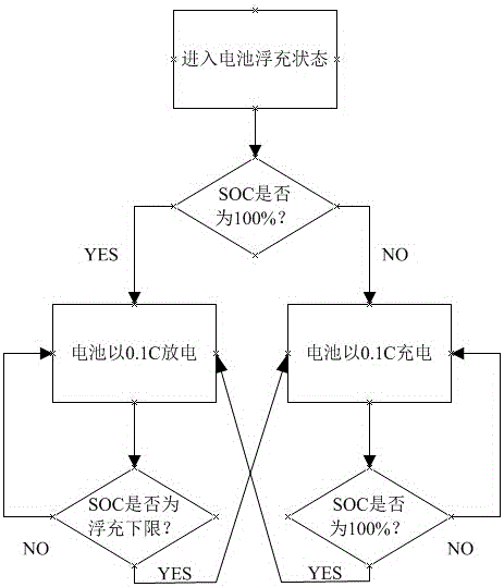
[0035] A battery floating charge method implemented in the present invention, its control flow is shown in figure 1 , first the control module confirms that the UPS is not working in the emergency power supply state, and the system enters the floating charge standby state. Judging the SOC of the battery or battery pack, if it is 100%, discharge at 0.1C to the lower limit of floating charge. The lower limit can be manually set but should not exceed the range of shallow charge and shallow discharge. After reaching the lower limit, continue to cycle charge and discharge at 0.1C. If the SOC of the battery or battery pack is not 100%, charge it to 100% with 0.1C current, and then continue to cycle charge and discharge at 0.1C.

[0036] The above-mentioned ups can be a single battery or a battery pack.

[0037] In order to ensure the safety of the battery o...


PUM


Abstract

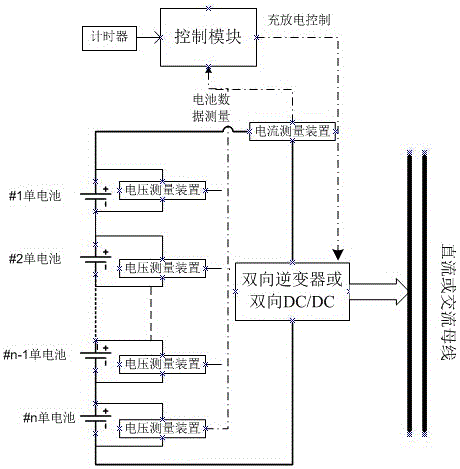
The invention discloses a floating charging method and a floating charging system for a battery. A voltage measurement device and a current measurement device are used for measuring battery data, a control module and a two-way inverter or a two-way DC / DC (direct current / direct current) converter are used for controlling charging and discharging, whether an SOC (state of charge) of the battery is in a set cycle capacity range or not is judged when the battery is in a floating charging standby state, and cyclic charging and discharging are controlled according to a floating charging lower limit, so that the battery or a battery pack is always in an online state. The method and the system are applied to occasions where the battery is required to keep online rapid response, such as a UPS (uninterrupted power supply) and an EPS (electric power supply).

Description

technical field [0001] The invention belongs to the field of battery applications, in particular to a method and system for floating charging of batteries. Background technique [0002] With the continuous progress of society and the further improvement of automation, more and more occasions have applied power equipment such as EPS emergency power supply and UPS uninterruptible power supply. In case of sudden natural disasters or other emergencies, the mains power supply stops, and these power supplies can supply power to fire-fighting facilities, security facilities, medical equipment, emergency lighting, important servers, automation control modules, etc., to ensure the safety of some important equipment. continue working. Because some equipment such as computers can tolerate a very short power outage time, most UPS and EPS need to achieve seamless switching. In order to achieve this goal, most of the internal batteries of the power supply are directly connected to the bu...

Claims


Application Information

Patent Timeline
Patent Type & Authority Patents(China)
IPC IPC(8): H01M10/44H02J7/00
CPCH01M10/4285H01M10/448Y02E60/10
Inventor 王珂李玉龙侯晓宝王睿李明科
Owner DONGFANG ELECTRIC CORP LTD
Learn More