
Method and system for converting time domain signals into frequency domain signals

A technology of time-domain signals and frequency-domain signals, applied in the direction of complex mathematical operations, etc., can solve the problems of small amount of calculation, difficulty in obtaining high-frequency accuracy and high-time-accuracy time-frequency distribution diagrams, etc., to improve frequency domain resolution accuracy or Effect of Time Domain Resolution Accuracy

Active Publication Date: 2014-09-17
刘湘辉
View PDF5 Cites 14 Cited by
  • Summary
  • Abstract
  • Description
  • Claims
  • Application Information

AI Technical Summary

Problems solved by technology

[0004] The short-time Fourier transform has the characteristics of fast speed and small amount of calculation, but the time-frequency distribution diagram generated by it, the number of frequency division points is always equal to half the length of the data frame, which is uniformly distributed, and because the power value reflects Each frame of data corresponds to the average value in the time slice, and the time response accuracy for instantaneous changes can only reach 1 / 2-1 / 5 of the duration of each frame
Therefore, given a sampling frequency, the product of the time precision and frequency precision of the transformed time-frequency distribution map is basically a constant value, and we can only be forced to make a compromise between time precision and frequency precision, and it is difficult to obtain Time-Frequency Profile with High Frequency Accuracy and High Time Accuracy

Method used


Image

  • Method and system for converting time domain signals into frequency domain signals
  • Method and system for converting time domain signals into frequency domain signals
  • Method and system for converting time domain signals into frequency domain signals

Examples


Embodiment Construction

[0035] In the following description, many technical details are proposed in order to enable readers to better understand the application. However, those skilled in the art can understand that without these technical details and various changes and modifications based on the following implementation modes, the technical solution claimed in each claim of the present application can be realized.

[0036] In order to make the purpose, technical solution and advantages of the present invention clearer, the following will further describe the implementation of the present invention in detail in conjunction with the accompanying drawings.

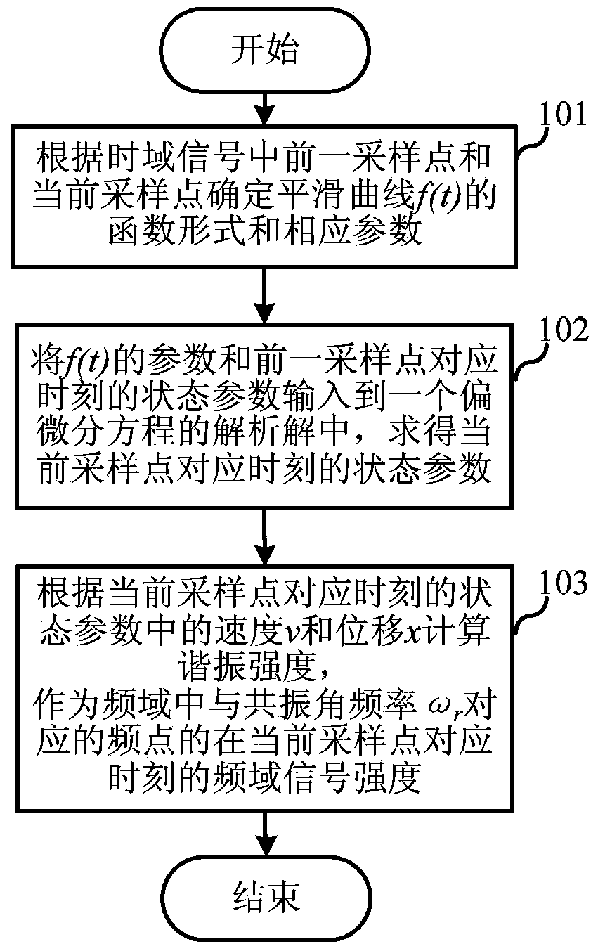
[0037] The first embodiment of the present invention relates to a method for converting a time-domain signal into a frequency-domain signal. figure 1 It is a schematic flowchart of the method for converting a time-domain signal into a frequency-domain signal.

[0038] Specifically, as figure 1 As shown, the method for converting a time-domain si...


PUM


Abstract

The invention relates to the field of digital signal processing, and discloses a method and a system for converting time domain signals into frequency domain signals. According to the method, the time domain signals are subjected to curve smoothening and are then regenerated into approximate simulation signals to be transmitted to a resonance system carrying out damped forced simple harmonic vibration, and in addition, the resonance intensity of the resonance system is calculated and is used as the intensity of the frequency domain signals. Any frequency point can be selected for calculation, so when only the signals of one special frequency point or several special frequency points need to be calculated, the calculation quantity is much lower than that of the traditional calculation method. Further, a time-frequency distribution diagram is obtained through calculating the frequency domain signal intensity change process, and the frequency domain signal intensity of the frequency point can be obtained through superimposing the frequency domain signal intensity at the corresponding moments of all sampling points of the corresponding frequency points, so the time domain signals are successfully converted into the frequency domain signals. The calculation is carried out on each sampling point one by one, so the time response can reach up to the sampling period, and in addition, the response amplitude is adjustable.

Description

technical field [0001] The invention relates to the field of digital signal processing, in particular to a method and system for converting time-domain signals into frequency-domain signals. Background technique [0002] Fast Fourier transform is currently one of the most commonly used processing methods for digital signal data. It can transform the signal from the time domain to the frequency domain and generate a statistical spectrum for further research. In order to study the frequency-changing signals such as speech information, time-frequency transform methods have been developed. Time-frequency transform method At present, some main methods are short-time Fourier transform, wavelet transform, and Wigner-Ville transform, etc., but the most important method is short-time Fourier transform. [0003] The specific method of Short Time Fourier Transform is to divide the digital signal into fixed-length frames, and there is 50% to 90% overlap between adjacent frames. Perfor...

Claims


Application Information

Patent Timeline
IPC IPC(8): G06F17/14
Inventor 刘湘辉
Owner 刘湘辉
Learn More