
Switchable parallax barrier panel and three-dimensional and planar switchable display panel

A parallax barrier and panel technology, which is applied in optics, instruments, nonlinear optics, etc., can solve problems affecting stereoscopic visual effects, and achieve the effect of reducing screen flickering

Inactive Publication Date: 2014-09-17
AU OPTRONICS CORP
View PDF3 Cites 1 Cited by
  • Summary
  • Abstract
  • Description
  • Claims
  • Application Information

AI Technical Summary

Problems solved by technology

However, there will be a gap between the light-transmitting area and the light-impermeable area on the parallax barrier panel, so that the light leakage caused by the gap on the parallax barrier panel affects the stereoscopic effect

Method used


Image

  • Switchable parallax barrier panel and three-dimensional and planar switchable display panel
  • Switchable parallax barrier panel and three-dimensional and planar switchable display panel
  • Switchable parallax barrier panel and three-dimensional and planar switchable display panel

Examples


Embodiment Construction

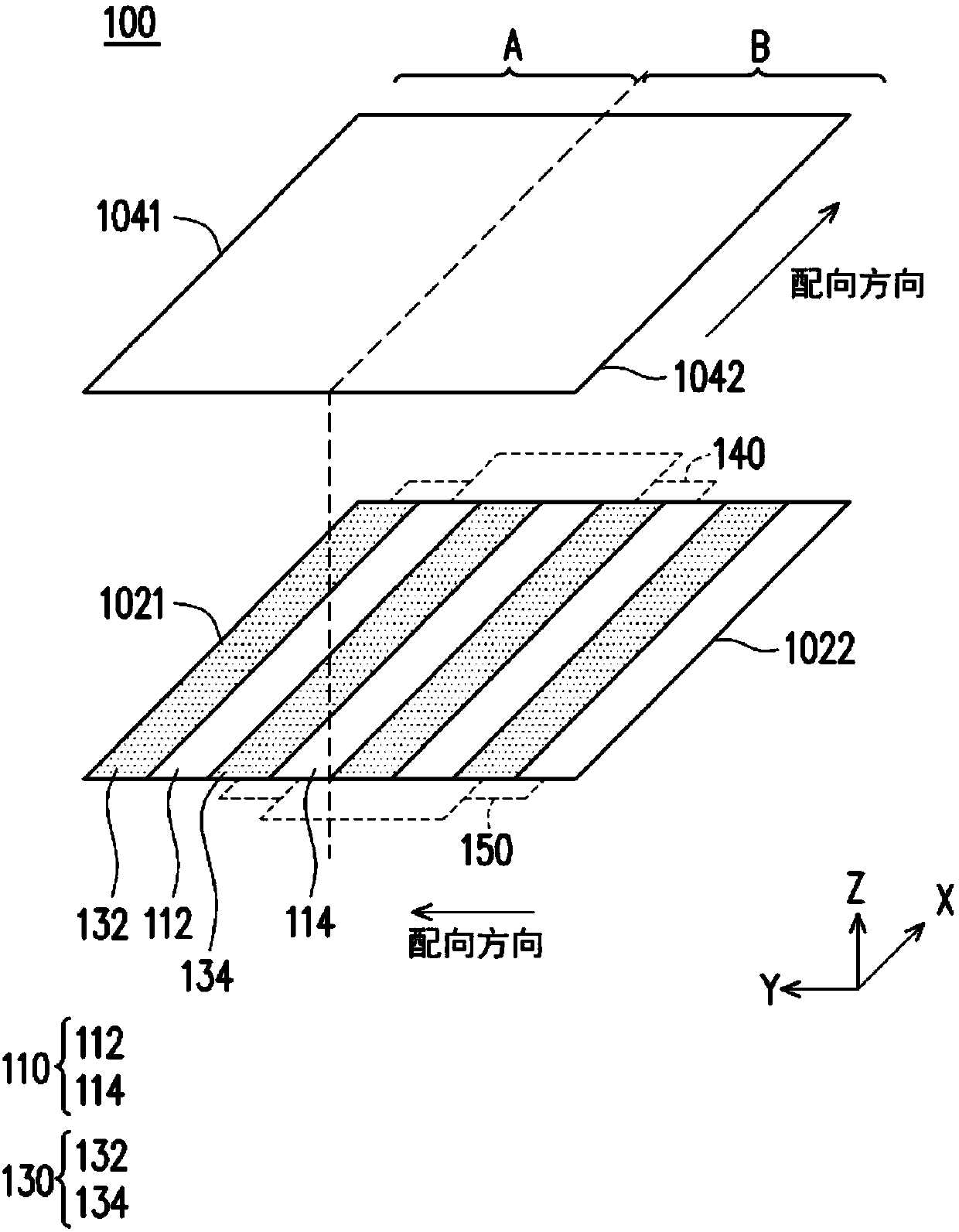
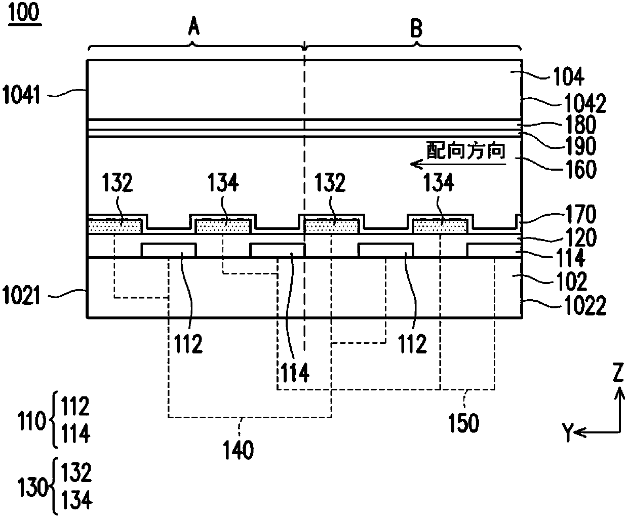
[0068] figure 1 is a schematic diagram of a switchable parallax barrier panel according to the first embodiment of the present invention. figure 2 yes figure 1 Sectional view in the vertical X direction. Please also refer to figure 1 and figure 2 , The switchable parallax barrier panel 100 of the present invention includes a first substrate 102, a second substrate 104, a first electrode 110, a first insulating layer 120, a second electrode 130, a first connection line 140, a second connection line 150 and a liquid crystal Layer 160. The first substrate 102 and the second substrate 104 are arranged corresponding to each other, and the first substrate 102 and the second substrate 104 are defined with sequentially arranged first regions A and second regions B, which means that there will be a plurality of sequentially staggered regions. The first zone A and the second zone B, such as: ABABABAB or BABABABA etc. are arranged, as long as one of the above-mentioned ones is sel...


PUM


Abstract

The invention discloses a switchable parallax barrier panel and a three-dimensional and planar switchable display panel. The barrier panel comprises a first substarte, a second substrate, a first electrode, a first insualting layer, a second electrode, a first connecting wire, a second connecting wire and a liquid crystal layer. The first substarte and the second substrate are arrayed in a corresponding mode.A first area and a second area, seuqntially arrayed, are defined on the first substarte and the second substrate. The first electrode at least comprises a first electrode and a second electrode which are mutually-parallel and arranged on the first substrate of a first area and the second substrate of a second area. The first insualting layer covers the first substatre and the first electrode. The second electrode at least comprises a third electrode and a fourth electrode which are mutually-parallel and arranged on the first insulating layer of the first area and the first insulating layer of the second area. The first connecting wire and the second connecting wire are arranged on the first substrate. The first connecting wire is connected with the first electrode and the third electrode. The second connecting wire is connected with the second electrode and the fourth electrode. The liquid crystal layer is clamped between the first substrate and the second substrate.

Description

technical field [0001] The present invention relates to a parallax barrier panel, and in particular to a switchable parallax barrier panel and a three-dimensional and planar switchable display panel. Background technique [0002] Stereoscopic display technologies can be roughly classified into auto-stereoscopic, in which viewers can directly watch with naked eyes, and stereoscopic, in which special-designed glasses are required to watch. The working principle of the naked-eye stereoscopic display is mainly to use an optical element to control the images received by the viewer's left eye and right eye. According to the visual characteristics of the human eye, when the left and right eyes watch two images with the same image content but with different parallax, the human eyes will overlap the two images and interpret them as a stereoscopic image. [0003] Most of the optical elements currently used to generate parallax images use parallax barrier panels, and the light-transmi...

Claims


Application Information

Patent Timeline
Patent Type & Authority Applications(China)
IPC IPC(8): G02F1/1343G02B27/22
Inventor 吴宣毅廖仁伟
Owner AU OPTRONICS CORP
Learn More