
Method for operating an electric fuel pump

A fuel pump and voltage technology, applied in fuel injection pump, fuel injection control, electrical control, etc., can solve the problem of high cost

Active Publication Date: 2018-07-24
ROBERT BOSCH GMBH
View PDF8 Cites 0 Cited by
  • Summary
  • Abstract
  • Description
  • Claims
  • Application Information

AI Technical Summary

Problems solved by technology

However, the voltage required for the operating point at the fuel pump varies strongly in different cases and depending on the ambient conditions
The design of the injection system therefore requires a permissible large voltage range of the electric fuel pump, however, in exceptional cases, for example, at the fuel filter, this can result in significantly higher, current on fuel pump
However, the design of the output stage of the electric fuel pump for this maximum possible current within the injection system is relatively more expensive than the design of the current that occurs only under normal conditions.

Method used


Image

  • Method for operating an electric fuel pump
  • Method for operating an electric fuel pump
  • Method for operating an electric fuel pump

Examples


Embodiment Construction

[0022] The invention is shown schematically on the basis of an embodiment in the drawing and is described in detail below with reference to the drawing.

[0023] The drawings are generally and collectively described, like reference numerals referring to like parts.

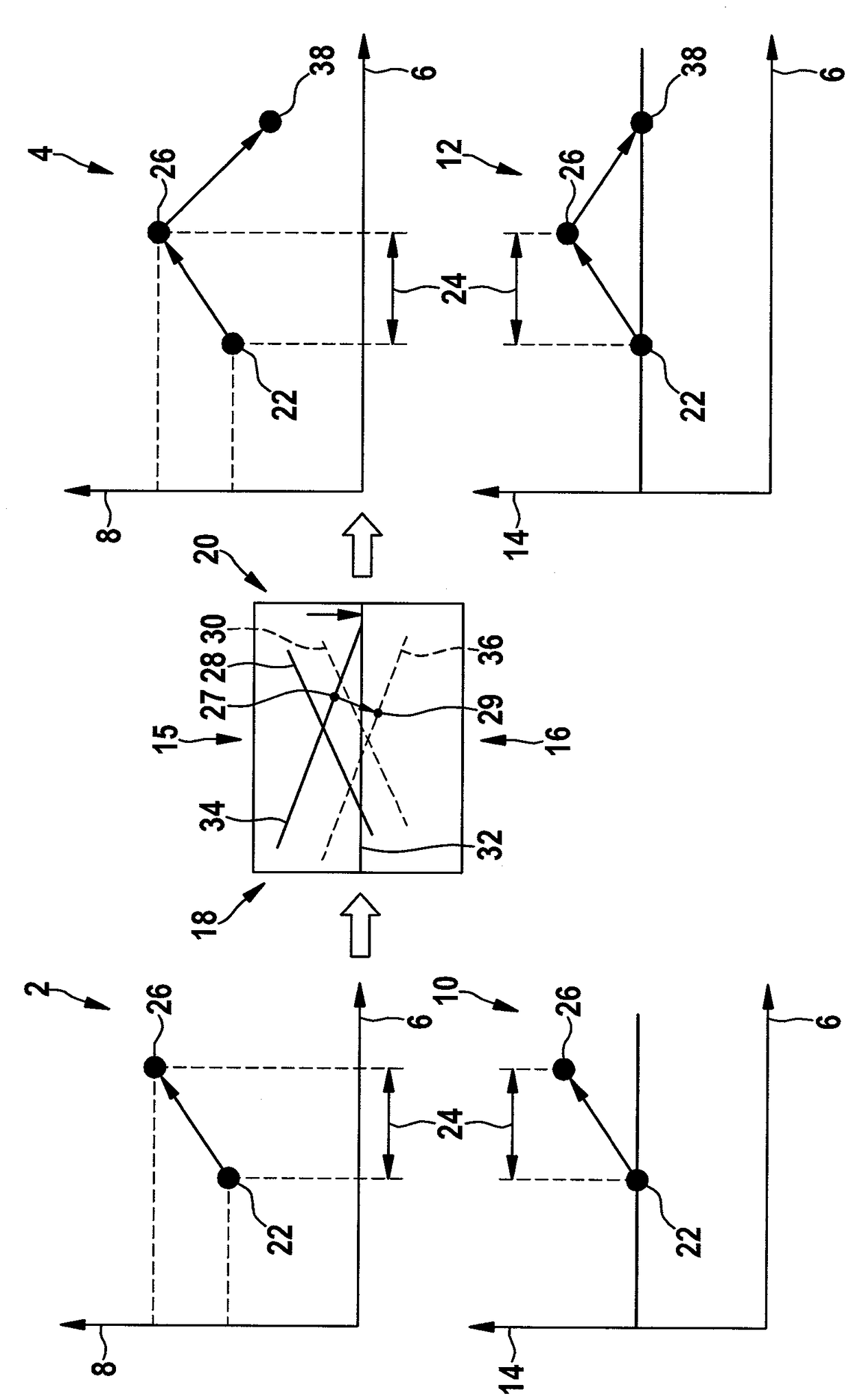
[0024] figure 1 Overall there are five graphs, namely a first pressure-time graph 2 and a second pressure-time graph 4 , in which the time in milliseconds is each recorded along the abscissa 6 and the time in bar is each recorded along the ordinate 8 Fuel pressure in injection equipment. also figure 1 A first current-time diagram 10 and a second current-time diagram 12 are shown, which likewise each have an abscissa 6 along which the time in milliseconds is recorded. Furthermore, the two current-time diagrams 10 , 12 each include an ordinate 14 along which the current flowing through the electric fuel pump of the injection system is recorded in amperes. In the middle between the first pressure-time diagram 2 a...


PUM


Abstract

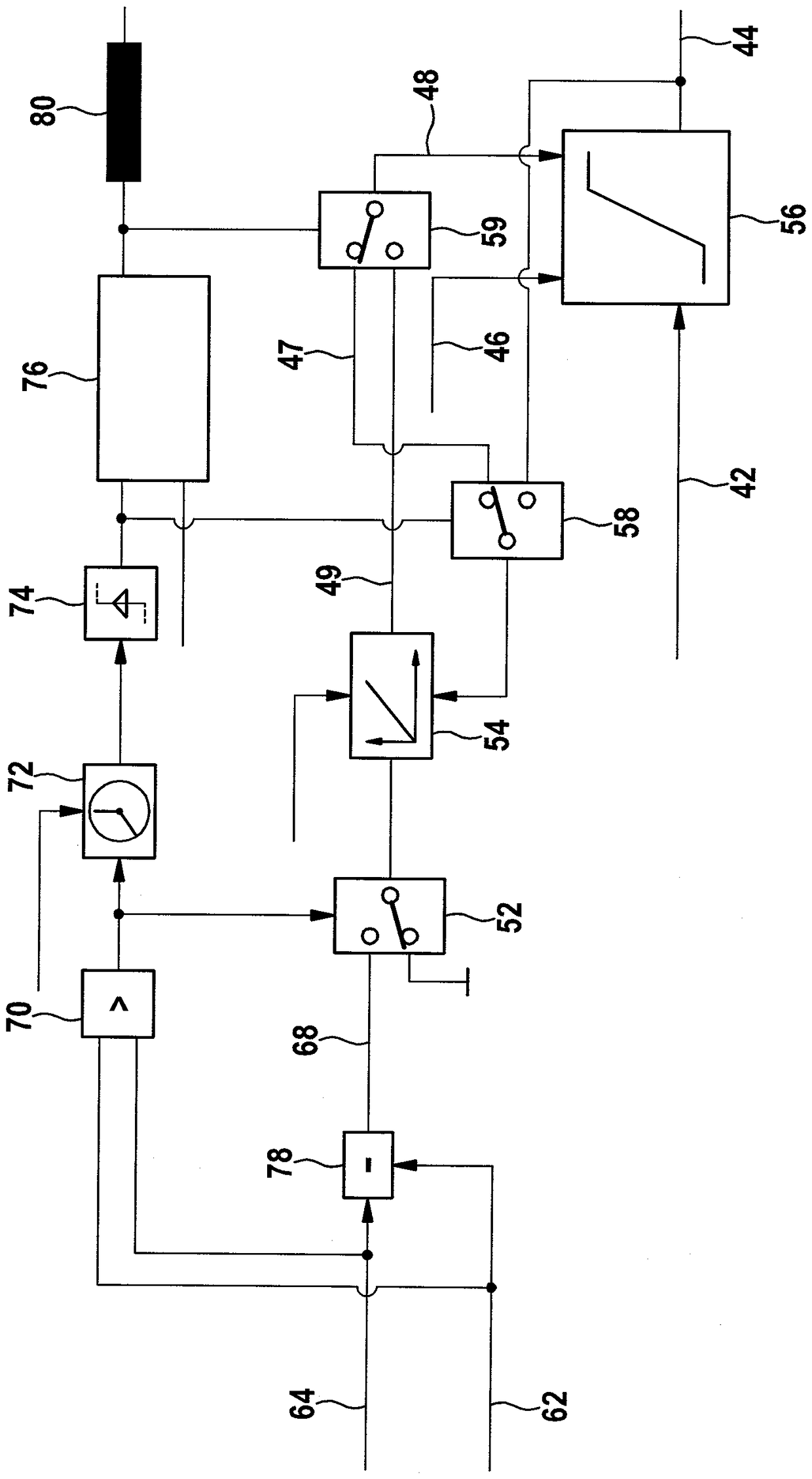
The invention relates to a method for operating an electric fuel pump, in particular an electric fuel pump of an injection system, wherein a maximum limit value ( 48 ) is preset for the voltage applied to the electric fuel pump, for the flow A preset maximum limit value (62) for the electric current of the fuel pump, wherein the value (62) of the current required by the electric fuel pump is measured, wherein the measured value (62) for the current exceeds the preset maximum limit value ( In the case of 64), the preset maximum limit value (48) for the voltage applied to the electric fuel pump is reduced depending on the measured value (62) of the current.

Description

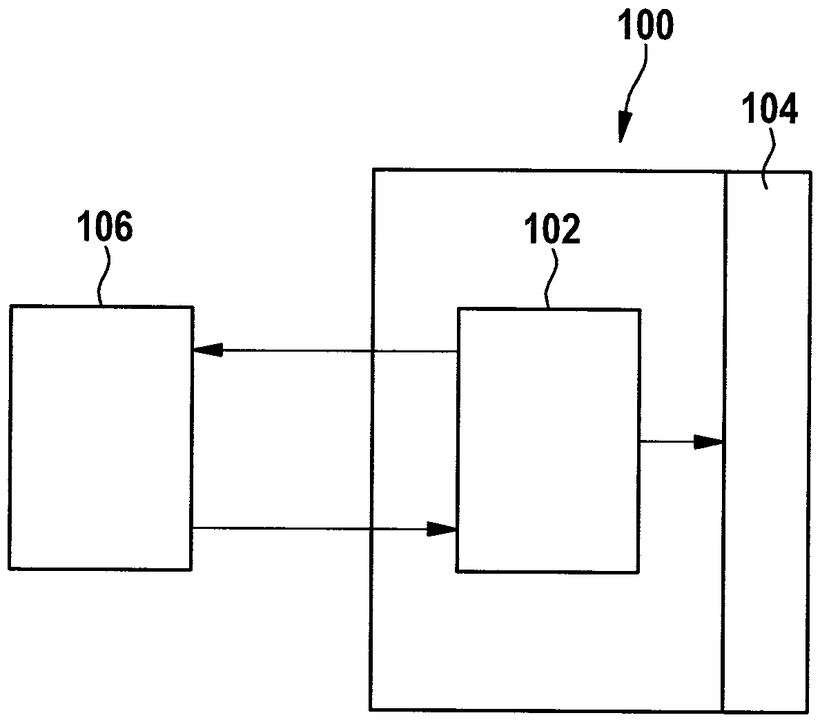
technical field [0001] The invention relates to a method and a control device for operating an electric fuel pump. Background technique [0002] The function of the injection system for the internal combustion engine can be controlled by the control device. A so-called EDC (Electronic Diesel Control) control device can be used for injecting diesel into the combustion chamber of the internal combustion engine. The output stage of the EDC control device is usually designed in such a way that the current requirements of the regulating components of the injection system can be met without problems even under unfavorable operating boundary conditions. In addition, a monitoring module is provided, with which the output stage can be switched off in the event of a fault, for example in the event of a short circuit or overheating. [0003] The regulating component of the injection system can be designed as an electric fuel pump (EKP), which in normal operation has only a limited cu...

Claims


Application Information

Patent Timeline
Patent Type & Authority Patents(China)
IPC IPC(8): F02D1/00
CPCF02D41/22F02D41/3082F02D2041/2048F02D2041/2051F02D2041/2058F02D2041/226
Inventor G.法伊特
Owner ROBERT BOSCH GMBH
Learn More