Improved oblique shock wave die structure for basin stand product

An improved and product technology, applied in the field of improved oblique punching die structure, can solve the problems of unbalanced spring force, reduce the service life of the die, stuck, etc., to avoid unbalanced force, prolong the service life, The effect of force balance

Inactive Publication Date: 2014-09-17
WUZHOU HENGSHENG ELECTRONICS
View PDF6 Cites 0 Cited by
  • Summary
  • Abstract
  • Description
  • Claims
  • Application Information

AI Technical Summary

Problems solved by technology

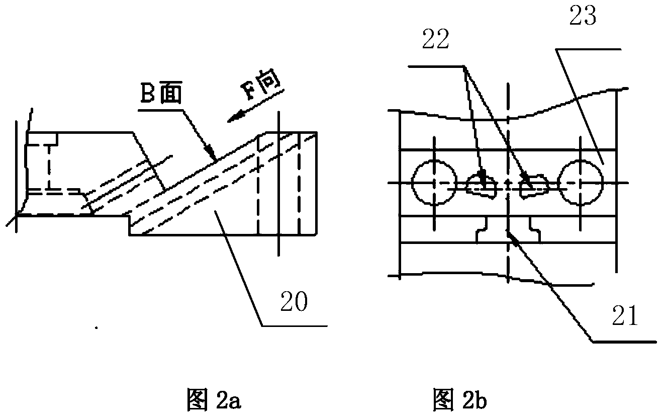
[0003] like figure 2 As shown, the punching method in the prior art adopts the chute structure of the slider and the guide rail plate. More precise guidance, accurate punching; but in the actual process of mold processing, it is necessary to ensure the parallelism and flatness of multiple surfaces at the same time, the processing is more difficult, and the ideal state cannot be achieved
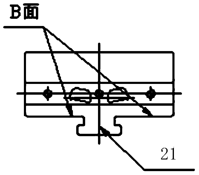
At the same time, when the material is returned, because there are too many contact surfaces, there is friction between the surfaces, so that the spring will produce unbalanced force when the material is returned. The force analysis of the structure is as follows: image 3 As shown, it includes stripping force F1, punch friction force F2, stripping spring force F3, self-gravity G and T-slot friction force F4. Since T-slot friction force F4 has many stress surfaces, in production practice The slider 23 and the punch are easily stuck in the guide rail plate 20, and when the punch is not completely withdrawn from the die and the mold starts to move upward, the mold will explode, which directly reduces the service life of the mold

Method used


Image

  • Improved oblique shock wave die structure for basin stand product
  • Improved oblique shock wave die structure for basin stand product
  • Improved oblique shock wave die structure for basin stand product

Examples


Embodiment Construction

[0021] The invention will be further described in detail below in conjunction with the accompanying drawings and specific embodiments.

[0022] refer to Figure 5 As shown, the improved oblique punching die structure of a pot frame product provided by the present invention includes an upper die, a lower die and a chute structure arranged between the upper die and the lower die, and the upper die includes an upper backing plate 1. The upper fixed plate 2 and the punch 9, the lower mold includes the die 5, the limit block 6, the lower backing plate 7, the backing plate 11 of the die, the chute structure includes the rail plate 3 and the slider 8, Described guide rail plate 3 is provided with inclined sliding surface, and this sliding surface is provided with guide groove, and described slide block 8 is provided with the guide block 15 that matches with guide groove, and described slide block 8 is also provided with convex The punch hole 13 that the mold 9 cooperates with each o...


PUM


Abstract

The invention relates to the technical field of dies, and discloses an improved oblique shock wave die structure for a basin stand product. The improved oblique shock wave die structure comprises an upper die, a lower die and a sliding chute structure arranged between the upper die and the lower die, wherein the upper die comprises an upper padding plate, an upper fixing plate and a male die; the lower die comprises a female die, a limiting block, a lower padding plate and a female die padding plate; the sliding chute structure comprises a guide rail plate and a sliding block, an oblique sliding face is arranged on the guide rail plate and provided with a guide groove, a guide block matched with the guide groove is arranged on the sliding block, and the sliding block is further provided with a male die via hole matched with the male die; the upper fixing plate is installed at the lower end of the upper padding plate, the upper end of the sliding block corresponds to the lower end of the upper fixing plate, the guide rail plate is located at the upper end of the limiting block, the female die is installed on the lower padding plate through the female die padding plate, the limiting block is installed on the lower padding plate, the sliding block is further provided with an elastic recovery device, and the guide groove and the guide block are of a square structure. The improved oblique shock wave die structure has the advantages that machining is easy to carry out, stress is balanced in the working process, and the service life of the dies is prolonged.

Description

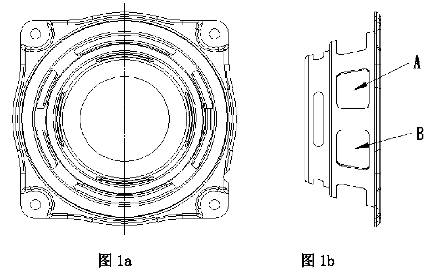
technical field [0001] The invention relates to the technical field of moulds, and more specifically relates to an improved oblique punching mold structure for pot frame products. Background technique [0002] Such as figure 1 As shown in , it is a structural diagram of an existing typical pot frame product, which is a stepped product with a slope in structure. In the production of continuous molds, excess material needs to be punched out at A and B to obtain windows. In the design of the mold structure, since the pot frame products have inclined surfaces, oblique punching is generally used for punching. [0003] Such as figure 2 As shown, the punching method in the prior art adopts the chute structure of the slider and the guide rail plate. More precise guidance and accurate punching; however, in the actual processing of the mold, it is difficult to ensure the parallelism and flatness of multiple surfaces at the same time, and the ideal state cannot be achieved. At the...

Claims


Application Information

Patent Timeline
Patent Type & Authority Applications(China)
IPC IPC(8): B21D28/14
Inventor 覃福庶
Owner WUZHOU HENGSHENG ELECTRONICS
Why Eureka
Try Eureka