
Test tube cleaning device

A technology for cleaning devices and test tubes, which is applied in the field of test tube cleaning devices and test tube cleaning devices, which can solve the problems of wasting manpower, trouble, and low efficiency, and achieve the effect of improving cleanliness and cleaning efficiency

Inactive Publication Date: 2014-09-17
张伟
View PDF5 Cites 12 Cited by
  • Summary
  • Abstract
  • Description
  • Claims
  • Application Information

AI Technical Summary

Problems solved by technology

[0002] At present, test tube cleaning is a simple but labor-intensive task, especially when a large number of test tubes need to be cleaned
At present, it is still cleaned manually, the efficiency is relatively low, and it is a waste of manpower. There is an urgent need for a batch cleaning device for test tubes, but there is no such device on the market

Method used


Image

  • Test tube cleaning device

Examples


Embodiment Construction

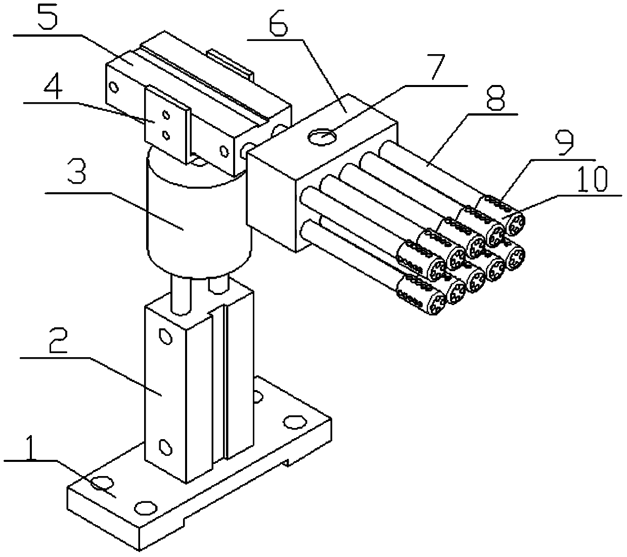
[0008] Such as figure 1 As shown, a test tube cleaning device includes a base 1, a first cylinder 2, a stepping motor 3, a cylinder fixing frame 4, a second cylinder 5, a water storage tank 6, a water injection port 7, a brush rod 8, and a water spray port 9 1. The brush head 10, the first cylinder 2 is fixed together with the base 1 by welding, installed above the base 1, the stepper motor 3 is installed above the piston rod of the first cylinder 2, and the second cylinder 5 is installed on the stepper motor 3 shaft Above, the water storage tank 6 is installed at the end of the piston rod of the second cylinder 5, the water injection port 7 is above the water storage tank 6, the brush rod 8 is installed on the side of the water storage tank 6, the brush head 10 is installed at the end of the brush rod 8, and the spray Nozzle 9 is around brush head 10.

[0009] When the device is working, place the test tubes to be cleaned horizontally in the test tube holding box, with the t...


PUM


Abstract

The invention relates to the field of experiment equipment, in particular to a test tube cleaning device. The test tube cleaning device comprises a base, a first air cylinder, a stepping motor, an air cylinder fixing frame, a second air cylinder, a water storage tank, water injecting ports, a brush rod, water spraying ports and a brush head, wherein the first air cylinder and the base are fixed together in a welding mode, the first air cylinder is installed on the upper portion of base, the stepping motor is installed above a piston rod of the first air cylinder, the second air cylinder is installed above a rotary shaft of the stepping motor, the water storage tank is installed at one end of a piston rod of the second air cylinder, the water injecting ports are formed in the upper surface of the water storage tank, the brush rod is installed on the lateral surface of the water storage tank, the brush head is installed at one end of the brush rod, and the water spraying ports are in the periphery of the brush head. The test tube cleaning device can assist in cleaning test tubes.

Description

technical field [0001] The invention relates to a test tube cleaning device, in particular to a test tube cleaning device composed of a water storage tank, a stepping motor, ten brush heads and two air cylinders. The invention relates to the field of experimental equipment. Background technique [0002] At present, test tube cleaning is a simple but labor-intensive task, especially when a large number of test tubes need to be cleaned. But still by manual cleaning at present, efficiency is relatively low, wastes manpower, and a kind of test tube batch cleaning device is urgently needed, but there is no such device on the market at present. Contents of the invention [0003] In view of the above-mentioned deficiencies, the present invention provides a test tube cleaning device. [0004] The present invention is achieved through the following technical solutions: a test tube cleaning device, including a base, a first cylinder, a stepping motor, a cylinder fixing frame, a se...

Claims


Application Information

Patent Timeline
IPC IPC(8): B08B9/36B08B9/34
CPCB08B9/34B08B9/36
Inventor 康立乾时超赵子宁伏永明常程井贵富韩强赵子敬王睿智高辉
Owner 张伟
Learn More