
System for monitoring puerperal uterus inner pressure in real time and using method thereof

A real-time monitoring system and internal pressure technology, applied in medical science, sports accessories, surgery, etc., to achieve the effects of sensitive and accurate measurement, simple and non-invasive operation, clinical practical promotion and application prospects

Inactive Publication Date: 2014-09-17
郑剑兰 +5
View PDF9 Cites 9 Cited by
  • Summary
  • Abstract
  • Description
  • Claims
  • Application Information

AI Technical Summary

Problems solved by technology

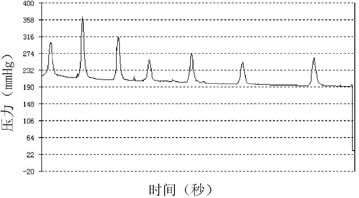
This monitoring method is simple and non-invasive, and can objectively evaluate uterine contractions, but so far there is only one article on postpartum intrauterine pressure measurement, reporting two cases of simultaneous monitoring of postpartum hemorrhage caused by uterine atony treated with Bakri balloon during cesarean section Intrauterine pressure (Georgiou C.Intraluminal pressure readings during the establishment of a positive'tamponade test'in the management of postpartum haemorrhage.BJOG,2010,117:295-303), as for the monitoring of the uterus after cesarean section and vaginal delivery Internal pressure methods have not been reported

Method used


Image

  • System for monitoring puerperal uterus inner pressure in real time and using method thereof
  • System for monitoring puerperal uterus inner pressure in real time and using method thereof
  • System for monitoring puerperal uterus inner pressure in real time and using method thereof

Examples


Embodiment Construction

[0032] The following embodiments will further illustrate the present invention in conjunction with the accompanying drawings.

[0033] see figure 1 , The postpartum intrauterine pressure real-time monitoring system embodiment of the present invention is provided with a postpartum intrauterine pressure measuring instrument 1 , a pressure gauge 2 and a data recording device 3 .

[0034]The postpartum intrauterine pressure measuring instrument 1 is provided with a uterine cavity blood drainage tube 11, a pressure measurement water injection tube 12, a balloon (also known as "postpartum intrauterine pressure measurement balloon") 13 and a fixing device 14; the uterine cavity blood drainage tube 11 and both ends of the pressure measurement water injection tube 12 are open, the top of the uterine cavity blood drainage tube 11 is provided with a uterine cavity blood drainage hole 111, and the pressure measurement water injection tube 12 is arranged on the inner side of the uterine ca...


PUM

PropertyMeasurementUnit
Diameteraaaaaaaaaa
Diameteraaaaaaaaaa
Diameteraaaaaaaaaa

Abstract

The invention provides a system for monitoring puerperal uterus inner pressure in real time and a using method of the system, and belongs to a medical monitoring system. The monitoring system is provided with a puerperal uterus inner pressure tester, a pressure gage and a data recording device. The puerperal uterus inner pressure tester is provided with a uterine cavity blood drainage tube, a pressure measuring water injection tube, a ball-shaped bag and a fixing device. The two ends of the uterine cavity blood drainage tube and the two ends of the pressure measuring water injection tube are open, the top end of the uterine cavity blood drainage tube is provided with a uterine cavity blood drainage hole, the pressure measuring water injection tube is located on one side in the cavity of the uterine cavity blood drainage tube, and the ball-shaped bag is located in the front of the uterine cavity blood drainage tube and below the uterine cavity blood drainage hole. The opening in the top of the pressure measuring water injection tube is located in the ball-shaped bag, the opening in the tail portion is connected with a first channel of a three-way valve, the ball-shaped bag can be filled with water through a second channel of the three-way valve, a third channel of the three-way valve is connected with a guide tube of the pressure gage, and the tail of the uterine cavity blood drainage tube is connected with a drainage bag. The fixing device is arranged on the rear portions of the uterine cavity blood drainage tube and the pressure measuring water injection tube, and the data output end of the pressure gage is connected with the input end of the data recording device through a data line.

Description

technical field [0001] The invention belongs to a medical monitoring system, in particular to a postpartum intrauterine pressure (intrauterine pressure, IUP) real-time monitoring system and its application method. Background technique [0002] Postpartum hemorrhage is the main cause of maternal death all over the world, and it is the first cause of maternal death in my country. 75% to 90% of postpartum hemorrhage is caused by uterine atony, but its diagnosis is lagging, and its treatment is mostly based on clinical experience, which is highly subjective. Therefore, it is difficult to diagnose and preventive treatment in time. Therefore, starting from the basics, it is very important to study the mechanism and measurement methods of postpartum hemorrhage caused by uterine atony during vaginal delivery. [0003] Intrauterine pressure (IUP) is one of the biomechanical indicators that indirectly reflect uterine tension and uterine smooth muscle relaxation and contraction activ...

Claims


Application Information

Patent Timeline
IPC IPC(8): A61B5/22A61B17/12
Inventor 郑剑兰付景丽陈辉东汪文雁李美莹周文光
Owner 郑剑兰
Learn More