
Pre-chamber system for an internal combustion engine

A technology of pre-combustion chamber and internal combustion engine, applied in the field of pre-combustion chamber system and internal combustion engine, can solve problems such as insufficient progress and achieve the effect of prolonging service life

Inactive Publication Date: 2014-09-10
GE JENBACHER
View PDF8 Cites 6 Cited by
  • Summary
  • Abstract
  • Description
  • Claims
  • Application Information

AI Technical Summary

Problems solved by technology

[0005] Disadvantages of such a system are, on the one hand, the tendency to generate carbon deposits in the so-called loss volume, which is the volume in which mixing is only insufficiently carried out, and, on the other hand, the disadvantage of the spark plug. The electrodes are strongly thermally loaded by the hot combustion gases

Method used


Image

  • Pre-chamber system for an internal combustion engine
  • Pre-chamber system for an internal combustion engine
  • Pre-chamber system for an internal combustion engine

Examples


Embodiment Construction

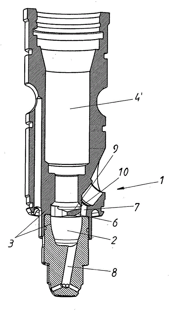
[0021] exist figure 1 A first embodiment of a prechamber system 1 according to the invention is shown in . In this case, the prechamber 2 is formed by a wall 3 and is connectable or connected in the assembled state via an ascending channel 8 to a combustion chamber (not shown) of the internal combustion engine. The ascending channel 8 opens into the prechamber 2 asymmetrically, thereby ensuring that a so-called tumble flow 14 is formed (see Figure 3b ).

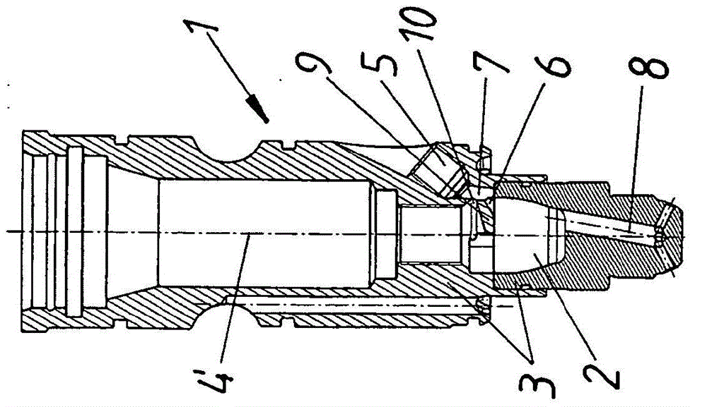
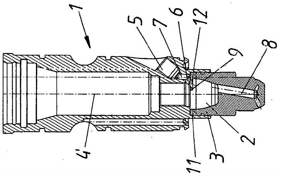
[0022] In wellbore 4', the figure 1 A spark plug 4 (but see FIG. 3 ), not shown in FIG. 1 , is inserted into the prechamber system 1 . A gas channel 7 will be in figure 1 The introduction device 5 not shown in (but see Figure 2a ) is connected to the pre-chamber 2 via the inlet opening 6 . A guide device 9 is arranged in the prechamber system 1 adjacent to the inlet opening 6 . Above the guide means 9 , a hole 10 is provided in the wall 3 of the prechamber 2 , said hole establishing a connection to the gas channel 7 ...


PUM


Abstract

Pre-chamber system (1) for an internal combustion engine with: - a pre-chamber (2) having a wall (3), - a spark plug (4) having at least one electrode (13), - a gas introduction device (5), particularly a gas valve, - a gas channel (7) connecting the gas introduction device (5) to the pre-chamber (2) via an inlet opening (6), - a rise channel (8) for connecting the pre-chamber (2) to a combustion chamber of the internal combustion engine, - a guiding device (9) for influencing the flow of the gas in the pre-chamber (2), said guiding device (9) being arranged adjacent to the inlet opening (6) in such a manner that in operation, a volume flow of hot gas flowing into the pre-chamber (2) via the rise channel (8) and reaching the electrode (13) of the spark plug (4) is reduced by the guiding device (9).

Description

technical field [0001] The invention relates to a prechamber system for an internal combustion engine having the features of the preamble of claim 1 and to an internal combustion engine, in particular a gas Otto engine, comprising such a prechamber system. Background technique [0002] A scavenged pre-chamber system is used in internal combustion engines starting from certain structural dimensions, the task of which is to ignite the combustion chambers of the internal combustion engine in such a way that ideal combustion takes place. During the intake stroke of the internal combustion engine, a defined amount of gas is added to the pre-chamber by the gas introduction device. [0003] At the same time, a stoichiometric gas-air mixture is supplied to the combustion chamber. The superstoichiometric mixture flows into the prechamber during the compression stroke through the communicating diversion opening (ascending channel) and is mixed there with the pure gas to form an appro...

Claims


Application Information

Patent Timeline
Patent Type & Authority Applications(China)
IPC IPC(8): F02B19/10F02B19/12F02B19/18F02M21/02
CPCY02T10/125F02B19/1014F02B19/18F02B19/1071F02M21/0281F02B19/12Y02T10/32F02P13/00F02B19/08Y02T10/12Y02T10/30
Inventor F·杜姆泽F·贝克尔
Owner GE JENBACHER
Learn More