Hybrid electromagnetic magnetic bearing switch reluctance motor

A technology of switched reluctance motor and reluctance motor, which is applied in the direction of electrical components, electromechanical devices, magnetic attraction or thrust holding devices, etc., and can solve the problems of large demand for suspension winding enameled wire, low power density, and low utilization of windings , to achieve the effects of good real-time control of current, strong high-speed adaptability, and large radial suspension force

Active Publication Date: 2014-09-10
NANJING UNIV OF POSTS & TELECOMM
View PDF2 Cites 4 Cited by
  • Summary
  • Abstract
  • Description
  • Claims
  • Application Information

AI Technical Summary

Problems solved by technology

[0003] The bearingless switched reluctance motor is a very complex and highly nonlinear system, there is a strong coupling between the torque and the suspension force, and it is difficult to realize the complete decoupling of the two in the control strategy and mathematical model, which is One of the main factors that make it difficult to improve the suspension and running performance of the bearingless switched reluctance motor
In addition, due to the need for suspension force control, the winding current must be controlled by chopping. When running at high speed, the dual effects of motion electromotive force and induced electromotive force make it impossible to perform tracking and chopping control on the current, that is, there will be a phenomenon that the chopping cannot be performed. This greatly affects the high-speed performance of the bearingless switched reluctance motor
[0004] In order to solve the above two shortcomings of the bearingless switched reluctance motor, scholars at home and abroad have done a lot of work, and proposed a mixed stator tooth single winding bearingless switched reluctance motor with 8 / 10 and 12 / 14 structures by changing the stator structure. It is characterized in that the suspension force and torque are separately generated by the suspension winding and the torque winding, the motor is a two-phase working system, and the power density of the motor is low; by changing the connection mode of the suspension winding, a series-excited double-winding bearingless switching magnetic switch is proposed. Resistance motor, which connects the three-phase levitation windings in the same direction in series into a set of windings, so that the magnetic permeability of the levitation winding remains constant in one rotor cycle, and the levitation current does not generate torque, which realizes the structural solution of torque and levitation force coupling, but the enameled wire of the suspension winding has a large demand, consumes copper, and the winding utilization is low; by increasing the rotor pole arc and changing the combination of the stator and rotor poles, the bearingless structure of 12 / 4, 12 / 8 and 16 / 4 poles is proposed Switched reluctance motor, however, the increase of the rotor pole arc compresses the torque output width, and the power density is low; by adding a radial magnetic bearing in the axial direction, a composite structure single-winding bearingless switched reluctance motor is proposed, however Each winding needs to be controlled independently during levitation operation, and the required power devices are relatively large. After the levitation excitation of one phase is completed, levitation force will still be generated due to the existence of asymmetric current, which is not conducive to the torque output of this phase and the torque output of the other phase. suspension control

Method used


Image

  • Hybrid electromagnetic magnetic bearing switch reluctance motor
  • Hybrid electromagnetic magnetic bearing switch reluctance motor
  • Hybrid electromagnetic magnetic bearing switch reluctance motor

Examples


Embodiment Construction

[0025] The technical scheme of the present invention is described in detail below in conjunction with accompanying drawing:

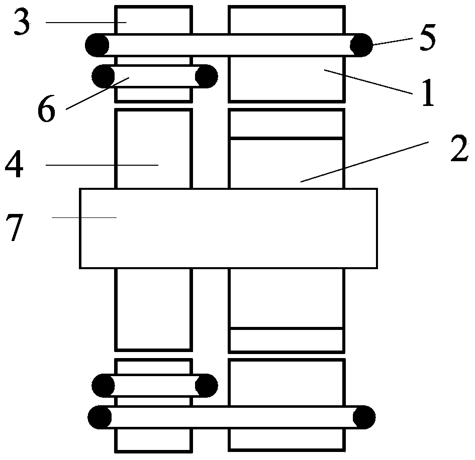
[0026] Such as figure 1 As shown, a structural schematic diagram of a hybrid electric excitation magnetic bearing switched reluctance motor of the present invention, wherein, 1 is the stator core of the reluctance motor, 2 is the rotor core of the reluctance motor, 3 is the stator core of the magnetic bearing, and 4 is the magnetic bearing Rotor core, 5 is the torque winding, 6 is the suspension force winding, 7 is the rotating shaft.

[0027] The motor stator is composed of a reluctance motor stator and a magnetic bearing stator, both of which have a salient pole structure, and the number of teeth is 12; the reluctance motor stator and the magnetic bearing stator are in a tooth-to-tooth alignment state, and both axial separated by a distance greater than the end length of the levitation force winding;

[0028] The motor rotor is composed of a relucta...


PUM


Abstract

The invention discloses a hybrid electromagnetic magnetic bearing switch reluctance motor. The hybrid electromagnetic magnetic bearing switch reluctance motor is composed of a motor stator, a reluctance motor rotor, a magnetic bearing stator, 12 torque windings, 12 suspension force windings and a rotating shaft; each of the reluctance motor stator and the magnetic bearing stator comprises 12 poles, the reluctance motor stator and the magnetic bearing stator are arranged in series in the axial direction, and a gap is formed there-between; the reluctance motor rotor comprises 8 poles, the magnetic bearing rotor is cylindrical, both the reluctance motor rotor and the magnetic bearing rotor sleeve the rotating shaft, and a gap which is equal to the distance between the magnetic bearing stator and the reluctance motor rotor is formed between the reluctance motor rotor and the magnetic bearing rotor; each torque winding winds a reluctance motor stator tooth and a magnetic bearing stator tooth in the same circumferential position, and each suspension force winding winds a magnetic bearing stator tooth. By means of the structure, the hybrid electromagnetic magnetic bearing switch reluctance motor realizes to decouple the torque and suspension force, and the radial bearing force is large; the influence of motion electromotive force on the suspension current chopping control is avoided, the real-time control effect of the current is good, and the high-speed adaptability is strong.

Description

technical field [0001] The invention belongs to the technical field of motors, and relates to a hybrid electric excitation magnetic bearing switched reluctance motor. Background technique [0002] The bearingless switched reluctance motor is a new type of magnetic levitation motor developed at the end of the 20th century. The double-winding bearingless switched reluctance motor is to stack the levitation winding that generates the levitation force and the winding of the original switched reluctance motor on the stator of the motor. By controlling the current of the two sets of windings, it has the ability to rotate and self-levitate simultaneously, so that Achieve ultra-high-speed operation of the motor. The single-winding bearingless switched reluctance motor has the ability to rotate and self-suspend at the same time by controlling the current of a set of windings. [0003] The bearingless switched reluctance motor is a very complex and highly nonlinear system, there is ...

Claims


Application Information

Patent Timeline
Patent Type & Authority Applications(China)
IPC IPC(8): H02K16/00H02N15/00
Inventor 刘泽远杨艳曹鑫邓智泉王世山
Owner NANJING UNIV OF POSTS & TELECOMM
Why Eureka
Try Eureka