
Intensity code based synthetic aperture laser radar system

A synthetic aperture laser and radar system technology, applied in the field of synthetic aperture laser radar, can solve the problems of complex signal source processing, low repetition frequency, and low broadband frequency modulation rate of nonlinear frequency modulation laser, etc., and achieve simple and easy-to-use modulation equipment, High-resolution, easy-to-achieve effects

Active Publication Date: 2014-09-10
SHANGHAI INST OF TECHNICAL PHYSICS - CHINESE ACAD OF SCI
View PDF6 Cites 16 Cited by
  • Summary
  • Abstract
  • Description
  • Claims
  • Application Information

AI Technical Summary

Problems solved by technology

However, the repetition rate is not high due to the low frequency modulation rate of broadband, and the linearity of broadband frequency modulation is poor. This method cannot be used for high-speed moving platforms such as airborne platforms with high distance resolution requirements, which limits the application of synthetic aperture lidar; nonlinear frequency modulation Laser signal source processing is relatively complex, and there are few studies; random code phase modulation lidar can realize fast signal modulation, but the modulation mechanism is complicated, and the phase modulation needs to be precisely controlled, and there are many restrictions on engineering implementation.
[0005] Based on the above, the biggest obstacle currently restricting the engineering of airborne synthetic aperture lidar lies in the inability to modulate a large time-width bandwidth product radar signal in a very short time (sub-millisecond)

Method used


Image

  • Intensity code based synthetic aperture laser radar system
  • Intensity code based synthetic aperture laser radar system
  • Intensity code based synthetic aperture laser radar system

Examples


Embodiment Construction

[0043] Specific embodiments of the present invention will be described in detail below in conjunction with the accompanying drawings. It should be understood that the specific embodiments described here are only used to illustrate and explain the present invention, and are not intended to limit the present invention.

[0044] The process of two-dimensional imaging of the target by the intensity-coded modulation synthetic aperture lidar system is divided into the following steps:

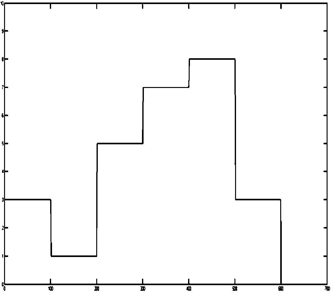
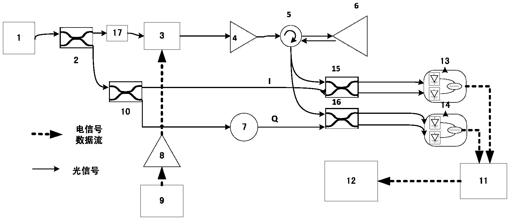
[0045] 1. Set the coded symbol width and symbol order, and select a random code sequence. This step sets the modulation information of the transmitted signal. Arbitrary waveform generator 9 chooses AWG5102C of Tektronix Company, sets the symbol width according to the distance resolution, and selects 5ns symbol width. The peak-to-peak value of the output level is set to 300mV, according to the 8-level intensity, that is, the output amplitude of the symbol is 300mV / 8*n, n=1,2,3...8. The symbol length i...


PUM


Abstract

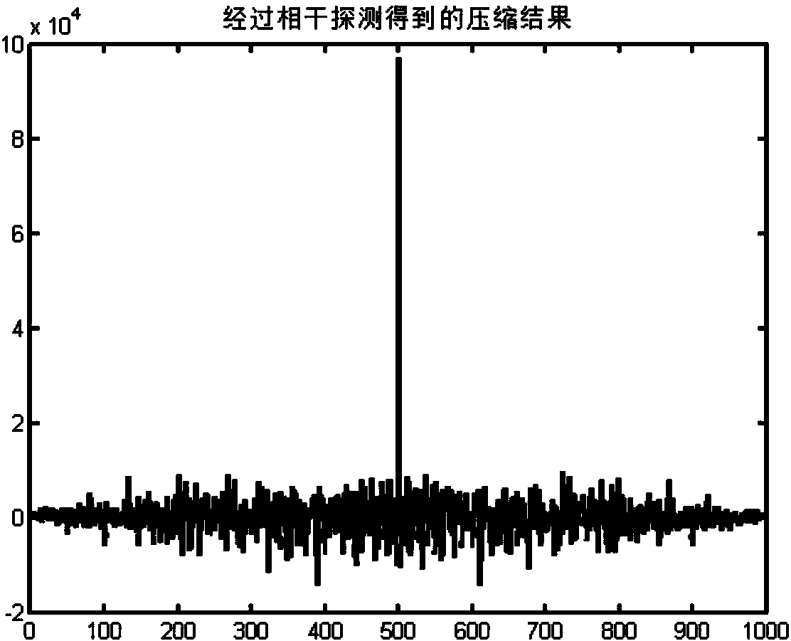
The invention discloses an intensity code based synthetic aperture laser radar system which is applied to synthetic aperture laser radar imaging. The intensity code based synthetic aperture laser radar system is formed by a code element signal generation unit, a 90 to 10 fiber coupler, a sending and receiving lens, a 50 to 50 fiber coupler, two balanced detectors, a data acquisition module and a signal processing program module. An echo signal is obtained by a heterodyne coherent detection and balance detection technology based on a multistage intensity laser code modulation pulse signal and a two-dimensional image of a target is obtained after distance direction and azimuth direction compression processing. According to the intensity code based synthetic aperture laser radar system, the signal modulation speed is high, the modulation bandwidth can reach more than 5 GHz under the condition that the requirements of the airborne platform flight speed are met, and the system is of a polarization-maintaining fiber structure and accordingly the amplitude stability is high, a light path is easy to adjust, the detection sensitivity is high, and the range resolution reaches the centimeter magnitude.

Description

technical field [0001] The invention relates to the field of synthetic aperture laser radar, in particular, to a synthetic aperture laser radar system based on an intensity-coded modulation signal. Background technique [0002] The current lidar system can be divided into direct detection lidar and coherent detection lidar according to the echo detection method. Direct detection has a simple structure and is the most widely used. This system calculates the distance by measuring the time delay (Δt) of the transmitted and received optical signals c is the speed of light, but to obtain high resolution, ultrashort pulses, high-speed sampling, and avalanche photodiodes with very high sensitivity must be used as detectors, which have relatively high requirements for devices and are greatly affected by noise. Coherent detection uses continuous local oscillator optical signals and echoes to mix on the detector. The detection sensitivity is high, and the echo frequency and phase ch...

Claims


Application Information

Patent Timeline
Patent Type & Authority Applications(China)
IPC IPC(8): G01S17/89G01S7/483
CPCG01S7/483G01S17/90
Inventor 舒嵘李飞张鸿翼洪光烈徐卫明吴军
Owner SHANGHAI INST OF TECHNICAL PHYSICS - CHINESE ACAD OF SCI
Learn More