Measuring method for phase of dual-wavelength micro-nano structure
A technology of micro-nano structure and phase measurement, which is applied in the direction of measuring devices, instruments, optical devices, etc., and can solve the problem of expanding the range of interferometric measurement
- Summary
- Abstract
- Description
- Claims
- Application Information
AI Technical Summary
Problems solved by technology
Method used
Image


Examples
Embodiment 1
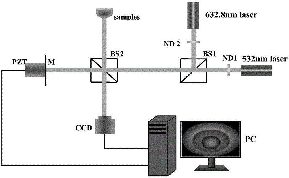
[0058] This example uses the figure 1 The Michelson interference optical path shown is a coaxial phase-shifted interferometric optical path, and the measured object is a commonly used optical element concave mirror. The measurement system includes a light source, a piezoelectric ceramic micro-displacement (PZT), a monochrome image sensor (CCD), and a computer (PC). Among them, the light source is composed of a He-Ne laser with a wavelength of 632.8nm and a solid-state laser with a wavelength of 532nm. The piezoelectric ceramic micro-displacement device is a micro-displacement device of the type 2D020 produced by the 26 Research Institute of the Electronic Industry Group, which is controlled by a computer to form a phase shift subsystem. The image sensor is the MTV-1082CB black and white industrial camera produced by Taiwan Mintong Company, and the image data is stored in the computer through the image acquisition card to form an image acquisition subsystem.
[0059] When imp...
Embodiment 2
[0068] In order to further prove that this method can be used for phase measurement of isolated discontinuous (with mutation) objects. The present embodiment adopts the method of simulation, applies the method of the present invention to measure the square column of isolated sudden change, as Figure 4a shown. The height of these square pillars is randomly generated within the range of 0-60000 nanometers, that is to say, there are random mutations between 0-60000 nanometers, and there is no correlation between them. The implementation steps are the same as figure 2 The flow chart shown. The height-wrapped grayscale images of these square columns acquired under a light source with a wavelength of 532 nm are shown in Figure 4b As shown, the height-wrapped grayscale image acquired under the light source with a wavelength of 632.8 nm is shown in Figure 4c shown. Subtract the two wavelength height wrapping images to obtain the difference grayscale image of height wrapping a...
Embodiment 3
[0070] The inventive method greatly expands the measuring range of interference precision measurement, according to the inventive method, if there is a greatest common divisor k between the measurement light source wavelengths that adopt, so the measuring range that this method can measure is: (λ 2 / k+1)λ 1 or (λ 1 / k+1)λ 2 . When the wavelength of the measuring light source is 632.8 nm and 532 nm, the greatest common divisor is 56. If the wavelength of 532 nm is used for reconstruction, the range can reach 60648 nm; if the wavelength of 632.8 nm is used for reconstruction, the range can reach 60748.8 nm. In order to prove the range of the method of the present invention, the present embodiment still adopts the method of simulation, and the method of the present invention is used to measure the slope of 0-60648 nanometer linear increase, and there are sudden changes on both sides of the slope, and the slope to be measured is as follows Figure 5a shown. A light source with...
PUM
| Property | Measurement | Unit |
|---|---|---|
| Wavelength | aaaaa | aaaaa |
| Wavelength | aaaaa | aaaaa |
Abstract
Description
Claims
Application Information
 - R&D
- Intellectual Property
- Life Sciences
- Materials
- Tech Scout
- Unparalleled Data Quality
- Higher Quality Content
- 60% Fewer Hallucinations
Browse by: Latest US Patents, China's latest patents, Technical Efficacy Thesaurus, Application Domain, Technology Topic, Popular Technical Reports.
© 2025 PatSnap. All rights reserved.Legal|Privacy policy|Modern Slavery Act Transparency Statement|Sitemap|About US| Contact US: help@patsnap.com