Sampling clock high-precision phase calibration and time reference determination method

A sampling clock and phase calibration technology, applied in satellite radio beacon positioning systems, measurement devices, instruments, etc., can solve the problems of receiver pseudo-range jump, not meeting the establishment time and hold time, and time relationship jump, etc. To achieve the effect of eliminating random phase changes

Active Publication Date: 2020-09-08
湖南中电星河电子有限公司
View PDF6 Cites 1 Cited by
  • Summary
  • Abstract
  • Description
  • Claims
  • Application Information

AI Technical Summary

Problems solved by technology

Since at the input of the receiving terminal, there is no high-rate sampling clock (f s ) and the phase relationship between the 1PPS signal, so there will be a high-rate sampling clock (f s ) sampling of the 1PPS signal does not meet the requirements of the setup time and hold time, which causes the time relationship between the local time and the time-frequency system to jump, and finally leads to the jump of the receiver pseudo-range

Method used


Image

  • Sampling clock high-precision phase calibration and time reference determination method
  • Sampling clock high-precision phase calibration and time reference determination method
  • Sampling clock high-precision phase calibration and time reference determination method

Examples


Embodiment 1

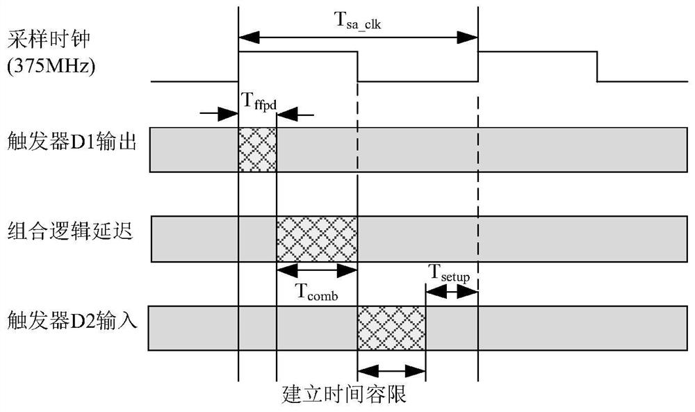
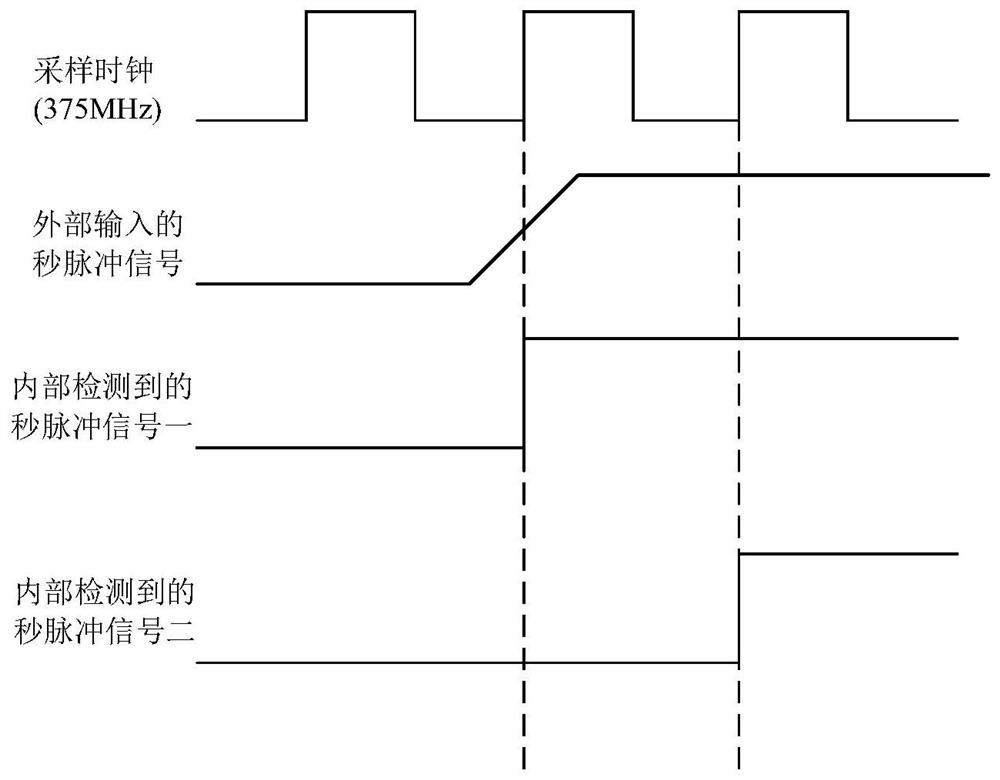
[0027] The application object of this embodiment is a satellite navigation ground station measurement communication system. The receiving terminal in the satellite navigation ground station measures the communication system by using the built-in frequency f osc The delay control module can implement (0.6+0.078*delay_value)ns delay control on the external input 1PPS signal, where delay_value is the delay counter value and 0≤delay_value≤31, then the minimum delay that can be achieved is 0.6ns, the maximum delay is 3.018ns. At the same time, the high-rate sampling clock frequency is f s , the period is 2.67ns, and the half period is 1.33ns.

[0028] The delay control module performs the delay control on the externally input 1PPS signal to obtain a 1PPS delayed signal. Use a high-speed sampling clock to sample 1PPS delayed signals with different delay values. When the 1PPS delayed signal is detected by the high-rate sampling clock (f s ) phase jump occurs during sampling, obt...

Embodiment 2

[0032] refer to Figures 5 to 7 The method for high-precision phase calibration and time reference determination of a sampling clock comprises the following steps:

[0033] (1) First read the data transmitted by the digital signal processor and write it into the corresponding register.

[0034] (2) If the register controlling the phase calibration is enabled, perform step 3, otherwise, directly perform step 5.

[0035] (3) Obtain the value of the phase jump of the 1PPS delay signal sampling, and update the worst delay register. The specific steps are as Image 6 Shown:

[0036] (3.1) The delay counter, clock counter and clock counter latch are all cleared to 0;

[0037] (3.2) Generate a 1PPS delay signal according to the delay formula (0.6+0.078*delay_value);

[0038] (3.3) using the rising edge of the 1PPS delay signal generated by the high-rate sampling clock detection step (3.2);

[0039] (3.4) obtain the corresponding clock counter value when step (3.3) detects the r...


PUM


Abstract

The invention provides a sampling clock high-precision phase calibration and time reference determination method. The delay control of different delay values is carried out on externally input 1PPS signals; 1PPS delay signals with different delay values are respectively sampled by using a high-speed sampling clock until the 1PPS delay signal with the phase jump is found, wherein the delay value corresponding to the 1PPS delay signal with phase jump is the worst delay value, the optimal delay value is calculated according to the worst delay value, the 1PPS delay signal corresponding to the optimal delay value is taken as the delay control 1PPS signal after final phase calibration, the delay control 1PPS signal is output, and the delay control 1PPS signal is subjected to sampling by a high-speed sampling clock. According to the invention, the problem of phase jump of the time reference (1PPS) at the high-rate sampling clock is solved, the phase relationship between the determined time reference (1PPS) and the high-rate sampling clock is finally ensured, and the output pseudo-range value of the receiver is finally ensured not to jump.

Description

technical field [0001] The invention belongs to the technical field of time synchronization, and in particular relates to a method for synchronizing the local time of a receiving terminal in a time-frequency signal digital processing part of an arbitrary system (such as a satellite navigation ground station measurement communication system) with a time-frequency system. Background technique [0002] The signal reception of the satellite navigation ground station measurement communication system uses the time reference 1PPS (1Pulse PerSecond, pulse per second) signal and the high-rate sampling clock (f s ) signal, in the time-frequency signal digital processing part, is to input high-rate sampling clock (f s ) sampling rate to sample the input 1PPS signal to realize the local time of the receiving terminal and the time synchronization of the time-frequency system. [0003] The clock is the most important and special signal in the whole circuit, and the actions of most device...

Claims


Application Information

Patent Timeline
Patent Type & Authority Applications(China)
IPC IPC(8): H04L7/00G01S19/24G01S19/03
CPCG01S19/03G01S19/24H04L7/0033H04L7/0087
Inventor 陈雷郭宇李井源黄仰博鲁祖坤
Owner 湖南中电星河电子有限公司
Why Eureka
Try Eureka