
C/C composite material deposition furnace

A composite material and deposition furnace technology, applied in the field of direct heating C/C composite material preparation, can solve the problems of complex equipment, long preparation cycle, and single workpiece form, and achieve low manufacturing cost and high reliability of current conduction , good temperature uniformity

Active Publication Date: 2014-09-10
XIAN AVIATION BRAKE TECH
View PDF7 Cites 0 Cited by
  • Summary
  • Abstract
  • Description
  • Claims
  • Application Information

AI Technical Summary

Problems solved by technology

[0007] In order to overcome the shortcomings of long preparation period, complex equipment or single form of workpieces in the prior art, the present invention proposes a C / C composite material deposition furnace

Method used


Image

  • C/C composite material deposition furnace
  • C/C composite material deposition furnace
  • C/C composite material deposition furnace

Examples


Embodiment Construction

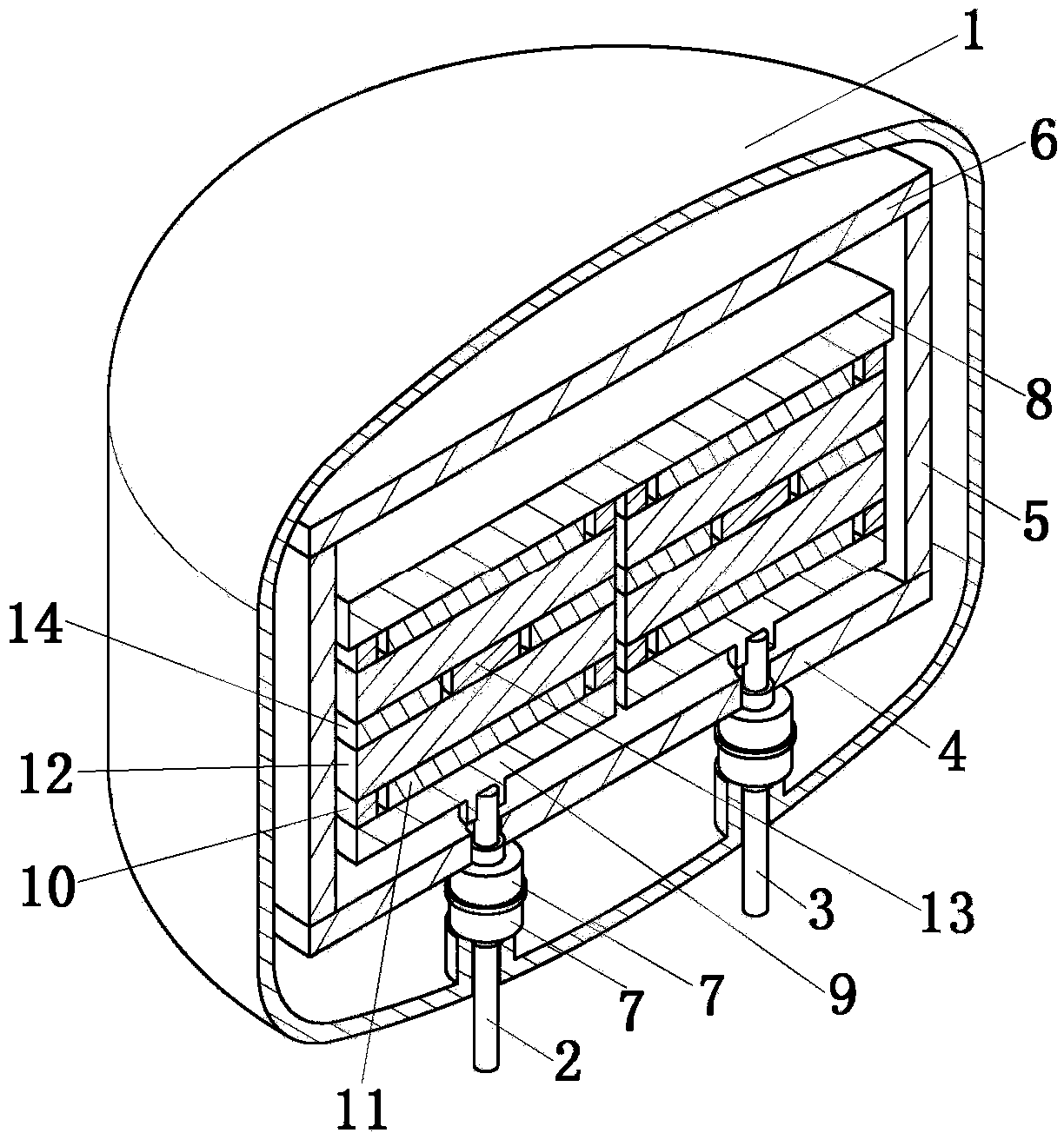
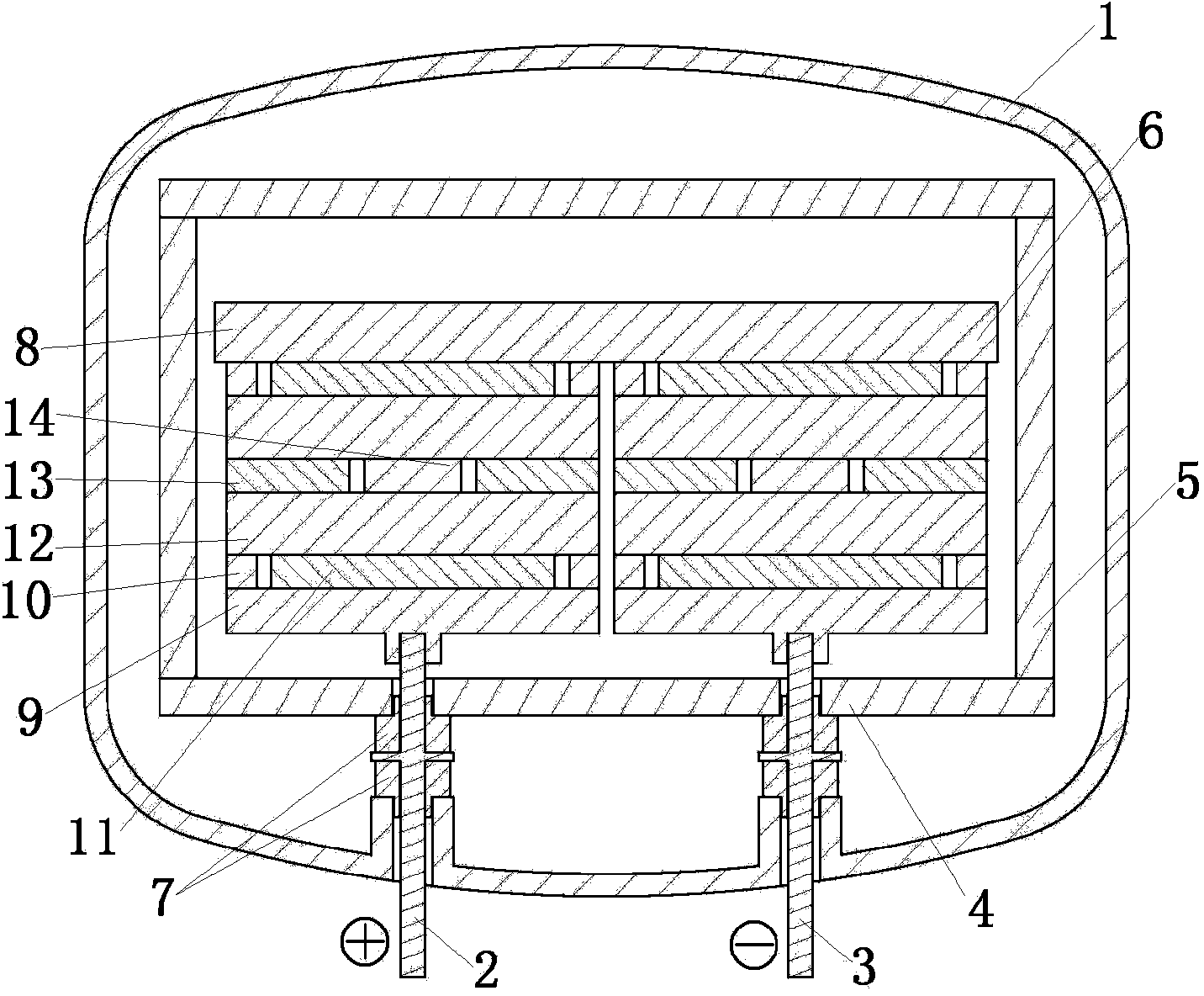
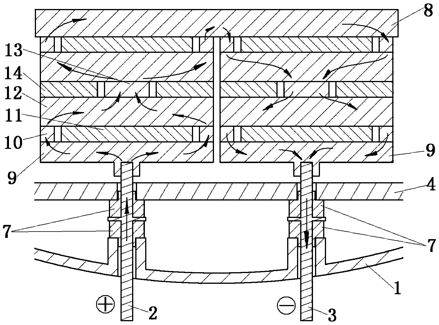
[0032] This embodiment is a C / C composite material deposition furnace with double columns.

[0033] This embodiment includes furnace shell 1, electrode rod, bottom plate 4, heat preservation barrel 5, heat preservation cover plate 6, pole plate insulation sleeve 7, conductive material tray 9, outer conductive ring 10, insulating sheet 11, workpiece 12, inner conductive sheet 13. An insulating ring 14 and a conducting plate 8 . The number of the electrode rods is the same as the number of the material columns. In this embodiment, there are two material columns, and the corresponding electrode rods are also two, which are respectively the first electrode rod 2 and the second electrode rod 3 . The number of the conductive material tray 9 and the conductive plate 8 is also the same as the number of the material column. The quantity of the outer conductive ring 10, insulating sheet 11, inner conductive sheet 13 and insulating ring 14 is determined according to the number of layer...


PUM


Abstract

The invention provides a C / C composite material deposition furnace. Various electrode bars are positioned between a bottom plate of a heat-insulation barrel and a bottom plate of a furnace shell; lower ends of the various electrode bars are respectively connected with a positive pole and a negative pole of a power source; upper ends of the various electrode bars are respectively connected with conductive trays of columns of various workpieces; conduction plates are respectively placed on the tops of the columns; and when the columns are stacked, the conductive trays are positioned on the bottommost layers of the columns, outer ring conductive layers, workpieces, center conductive layers, other workpieces and other ring conductive layers are sequentially placed on the conductive trays from bottom to top until the columns are stacked completely. Conductive bottom plates, conductive rings or sheets, the workpieces and the conduction plates are connected to one another in a gravitational pressing manner, so that a current channel is formed. The problems that a connecting mechanism is complex and is inconvenient to mount by using a clamped type connecting mode in the prior art, expansion and contraction characteristics of the workpieces are different from expansion and contraction characteristics of a clamping mechanism, so that current conduction reliability is poor are solved. The C / C composite material deposition furnace has the advantages of easiness in installation and connection and high current conduction reliability. The structure of the C / C composite material deposition furnace is simplified; and the manufacturing cost is low.

Description

technical field [0001] The invention belongs to the technical field of preparation of C / C composite materials, in particular to a preparation method of direct heating C / C composite materials. Background technique [0002] The preparation methods of C / C composite materials mainly include indirect heating and direct heating in terms of heating forms. [0003] Indirect heating is a kind of method that uses the resistance of the heating element to make the current flow through the heating element to heat the heating element first, and then use the thermal radiation and conduction of the heating element to reheat the workpiece, so that the workpiece reaches the deposition temperature for deposition. The method has the advantages of high temperature uniformity, many types of workpieces that can be heated, and mature technology, and is widely used in the technical field of C / C composite material preparation. [0004] At present, major international C / C composite material preparati...

Claims


Application Information

Patent Timeline
Patent Type & Authority Applications(China)
IPC IPC(8): F27B17/00
Inventor 卢杰张晓伟崔鹏刘海平张正参朱继泉
Owner XIAN AVIATION BRAKE TECH
Learn More