
A common rail injector

A common rail fuel injector and fuel injector technology, which is applied in the directions of machines/engines, fuel injection devices, engine components, etc., can solve the problem of poor fuel injection sensitivity of fuel injectors, long delay of fuel injector closing, and limited injection. The problem of multiple injection capability of the fuel injector can improve the assembly consistency, shorten the delay of fuel injection closing, and improve the sensitivity of fuel injection.

Active Publication Date: 2016-05-11
CHINA FAW LIMITED WUXI FUEL INJECTIONEQUIP RES INST +1
View PDF6 Cites 0 Cited by
  • Summary
  • Abstract
  • Description
  • Claims
  • Application Information

AI Technical Summary

Problems solved by technology

This causes the fuel pressure in the control chamber to decrease greatly, resulting in a slower recovery of the fuel pressure in the control chamber at the end of the injection, and a longer delay in the closing of the injector, resulting in poor fuel injection sensitivity of the injector , which limits the improvement of the injector's multiple injection capability

Method used


Image

  • A common rail injector
  • A common rail injector
  • A common rail injector

Examples


Embodiment Construction

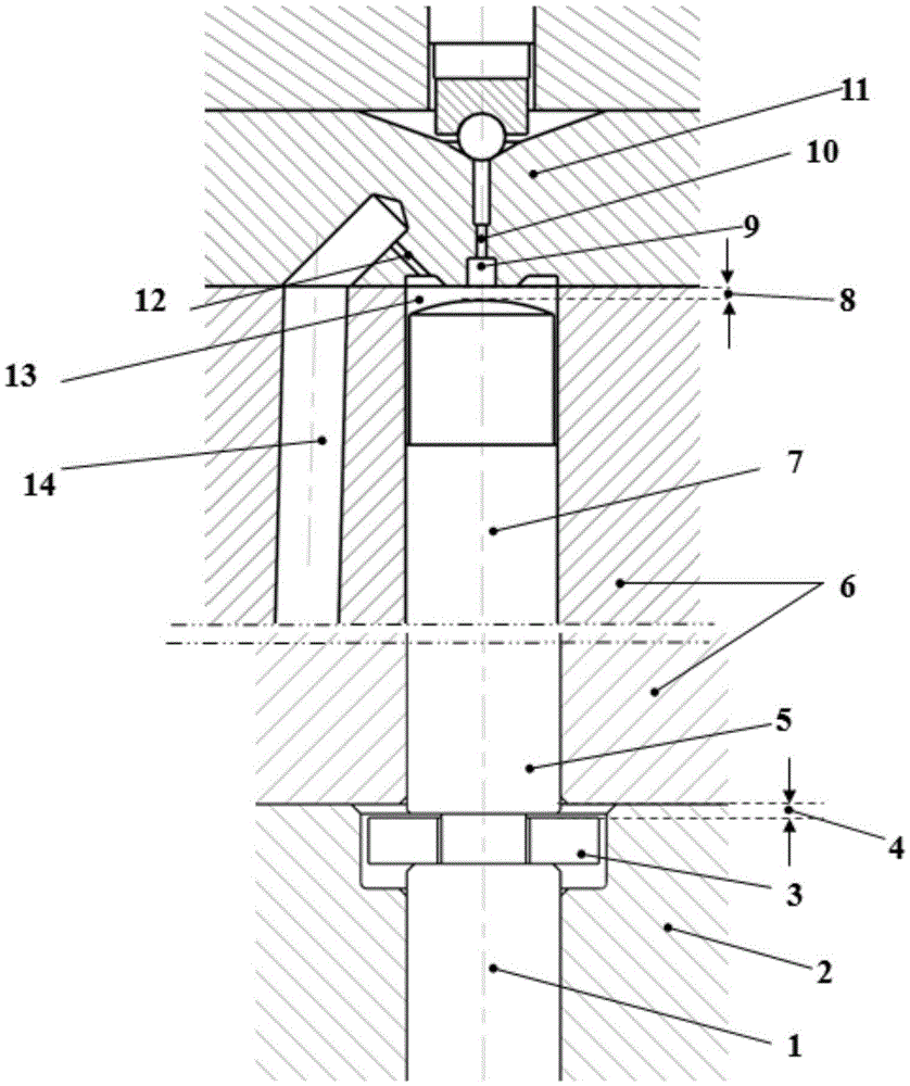
[0020] A kind of common rail fuel injector of the present invention can refer to attached figure 1 description of.

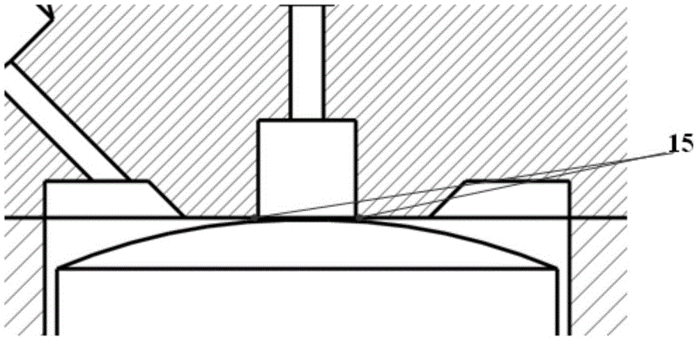
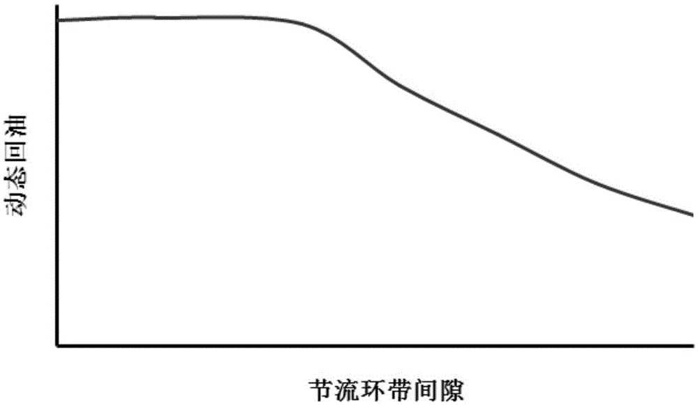
[0021] The control piston 7 of the fuel injector, the fuel injector body 6 and the orifice 11 form a control cavity 13 . The fuel injector controls the rise or fall of the fuel pressure in the control chamber 13, and then controls the upward and downward movement of the piston 7 in the axial direction through the pressure difference, thereby controlling the movement of the needle valve 1 to control the fuel injection process. By reducing the assembly gap 8 between the top of the control piston 7 and the bottom surface of the orifice plate 11, when the injector sprays oil, after the control piston 7 rises, a throttle ring is formed between the top of the control piston 7 and the bottom 11 of the orifice plate 15. The throttling effect is produced to greatly reduce the dynamic oil return of the injector (such as image 3 shown). In order to better exert the thr...


PUM


Abstract

The invention discloses a common-rail oil sprayer. The common-rail oil sprayer is characterized in that a control cavity comprises a control piston, an oil sprayer body and an orifice plate. The common-rail oil sprayer has the advantages that the shape of the bottom of the orifice plate and the shape of the top of the control piston are reasonably designed, so that throttle belts can be formed by the control piston and the bottom of the orifice plate when oil is sprayed by the oil sprayer, throttle effects can be realized, dynamically returned oil of the oil sprayer can be greatly reduced, heat generated by the oil sprayer can be decreased, and power loss of an oil supply pump can be reduced; throttle belt gaps between the bottom of the orifice plate and the head of the control piston are precisely designed, so that the piston is in a completely floating state after being completely lifted up; the throttle belt gaps between the control piston and the bottom of the orifice plate are automatically adjusted in a floating manner by the aid of hydraulic balance, so that pressure difference of the control cavity due to assembly errors and different throttle belt gaps can be reduced, and the assembly consistency of the oil sprayer can be improved.

Description

technical field [0001] The invention belongs to the field of fuel injection systems for internal combustion engines, and in particular relates to a common rail fuel injector. Background technique [0002] In order to meet increasingly stringent emission regulations, fuel system injection pressures are getting higher and higher. As the injection pressure increases, the dynamic oil return of the injector becomes larger and larger. The increase of the dynamic oil return of the injector will increase the energy consumption of the fuel supply pump and reduce the economy of the fuel system. At the same time, more high-pressure fuel leaks into the low-pressure oil circuit, which will lead to higher temperature of the low-pressure oil circuit in the injector, which will affect the stability and reliability of the injector. In addition, it can be seen from the working principle of the fuel injector that the fuel injector controls the rise or fall of the fuel pressure in the control...

Claims


Application Information

Patent Timeline
Patent Type & Authority Patents(China)
IPC IPC(8): F02M47/06
Inventor 郭立新夏兴兰缪雪龙杨海涛宋永平傅立运杨鹿
Owner CHINA FAW LIMITED WUXI FUEL INJECTIONEQUIP RES INST
Learn More