
Unmanned aerial vehicle system with in-site virtual-actual coupling

An unmanned aerial vehicle and field technology, applied in the field of unmanned aerial vehicles, can solve the problems of inability to significantly improve the crash of the flying unit, the difficulty of achieving consistent force feedback of the operating equipment, and the high risk of the first flight.

Inactive Publication Date: 2014-09-10
ACADEMY OF ARMORED FORCES ENG PLA
View PDF4 Cites 59 Cited by
  • Summary
  • Abstract
  • Description
  • Claims
  • Application Information

AI Technical Summary

Problems solved by technology

First of all, since the virtual simulation training system is configured in the laboratory, it cannot support the targeted guidance training of the users in the field
Second, the virtual UAV flight training operating equipment and the actual UAV system control equipment are separated from each other, and it is difficult to achieve the consistency between the force feedback of the operating equipment during virtual training and the real flight control equipment. In the face of actual installation, it still takes a while to adapt, so it cannot significantly improve the problem of flying unit crashes
Third, the flight of UAVs is greatly affected by natural conditions. When using indoor training, the environmental parameters are often calculated through assumptions or models. Deviation, so that the first flight is still not clear about the reasonable range of attitude control such as throttle and pitch, so the risk of the first flight is still very high

Method used


Image

  • Unmanned aerial vehicle system with in-site virtual-actual coupling
  • Unmanned aerial vehicle system with in-site virtual-actual coupling
  • Unmanned aerial vehicle system with in-site virtual-actual coupling

Examples


Embodiment Construction

[0047] In order to make the technical problems, technical solutions and beneficial effects solved by the present invention clearer, the present invention will be further described in detail below in conjunction with the accompanying drawings and examples. It should be understood that the specific examples described here are only used to explain the present invention, not to limit the present invention.

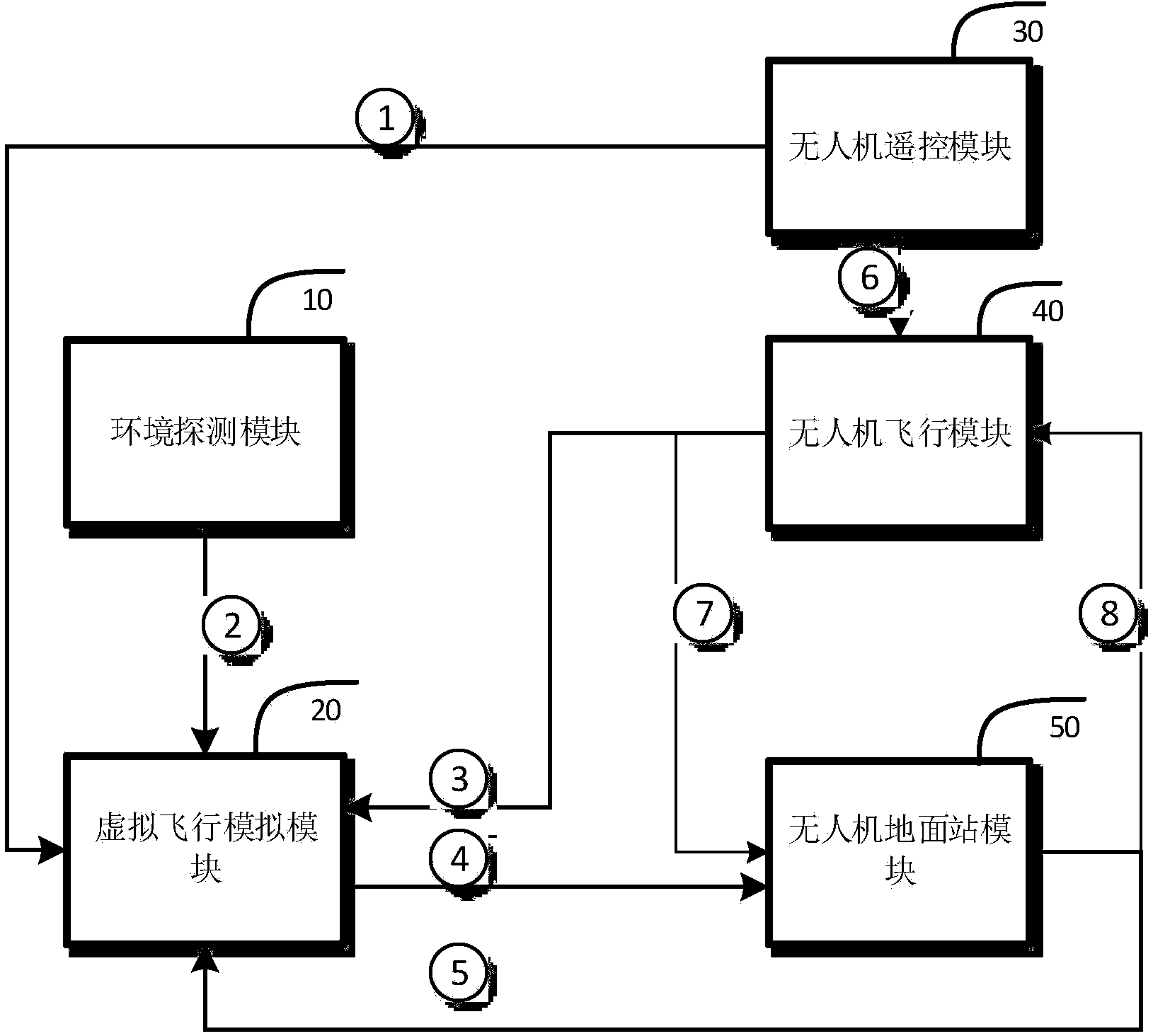
[0048] figure 1 It is a schematic structural diagram of the on-site virtual-real coupling UAV system provided by the present invention. In this implementation example, it includes an environment detection module 10 , a virtual flight simulation module 20 , a UAV remote control module 30 , a UAV flight module 40 , and a UAV ground station module 50 .

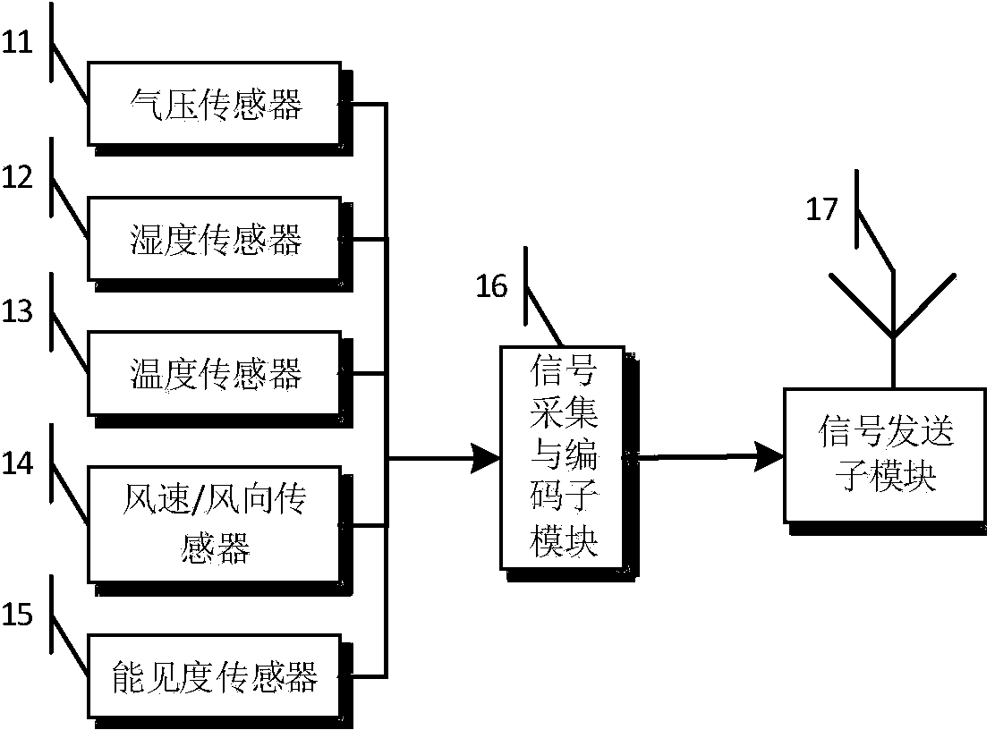
[0049] Such as figure 2 As shown, the environmental detection module 10 is composed of an air pressure sensor 11, a humidity sensor 12, a temperature sensor 13, a wind speed / wind direction sensor 14, a visibility sensor 15, a ...


PUM


Abstract

The invention relates to an unmanned aerial vehicle system with in-site virtual-actual coupling. The system comprises an environment detection module, a virtual flight simulation module, an unmanned aerial vehicle remote control module, an unmanned aerial vehicle ground station module and an unmanned aerial vehicle flight module, wherein the environment detection module is used for detecting varied environmental parameters of the actual flight environment of the site; the virtual flight simulation module is used for generating virtual training environment and a virtual unmanned aircraft; the unmanned aerial vehicle remote control module is used for generating and transmitting remote control commands for an unmanned flight unit, and the remote control commands can be received by the unmanned aerial vehicle flight module and the virtual flight simulation module; the unmanned aerial vehicle flight module is an actually-mounted unmanned aircraft; an unmanned aerial vehicle ground station is equipment which is placed on the ground, and use staff perform initialization and real-time information treatment on the actually-mounted unmanned aircraft or the virtual unmanned aerial vehicle aircraft through the unmanned aerial vehicle ground station, so that the initial route of the actually-mounted unmanned aircraft or the virtual unmanned aerial vehicle aircraft is programmed, and the position, the attitude parameter and the obtained video signal of the actually-mounted unmanned aircraft or the virtual unmanned aerial vehicle aircraft are received.

Description

technical field [0001] The invention relates to the field of unmanned aerial vehicles, in particular to an on-site virtual-real coupling unmanned aerial vehicle system. Background technique [0002] Unmanned Aerial Vehicle System (UVA) is a new type of equipment that is developing rapidly, and has been widely used in military and civilian applications. It is an important content of UAV system research to develop a new type of UAV system so that it has better performance and better safety. [0003] At present, the UAV system is mainly composed of flight unit, ground station unit and remote control unit. This structure is a work arrangement model that requires skilled personnel to operate. For novices, directly operating the existing UAV system can easily destroy the flight unit, resulting in large economic losses. In order to improve drone flight control skills and ensure the safety of the first flight, many units will conduct a period of training for novices. There are t...

Claims


Application Information

Patent Timeline
IPC IPC(8): B64F5/00
Inventor 徐丙立朱刚荆涛李媛州赵秀玉闫兴鹏刘军辉汪熙
Owner ACADEMY OF ARMORED FORCES ENG PLA
Learn More