Electrical impedance imaging device

A technology of electrical impedance imaging and circuits, which is applied in the field of medical detection, can solve the problems of complex hardware system, limited number of electrodes, unsatisfactory, etc., and achieve the effect of stable and reliable performance, not easy to rust and corrosion, and good conductivity

Inactive Publication Date: 2014-09-10
NANJING UNIV OF POSTS & TELECOMM
View PDF2 Cites 12 Cited by
  • Summary
  • Abstract
  • Description
  • Claims
  • Application Information

AI Technical Summary

Problems solved by technology

[0004] The main difficulties of the existing technology are mainly manifested in: the need to generate a current source with high precision and high output impedance; the current maximum achievable physiological impedance change can only cause a 10% change in the measured voltage, which requires the measurement of the electrical impedance imaging system The accuracy should be greater than 0.1%; the amount of information that can be

Method used


Image

  • Electrical impedance imaging device
  • Electrical impedance imaging device
  • Electrical impedance imaging device

Examples


Embodiment Construction

[0023] The present invention will be further described in detail below in conjunction with the accompanying drawings and specific implementation methods.

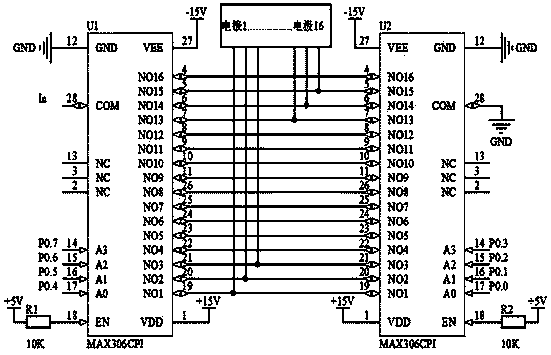
[0024] The present invention designs an electrical impedance imaging system based on a single-chip microcomputer control system. The structural principle of the system is as follows: figure 1 shown.

[0025] The signal generator (1) adopts MAXIM’s precision high-frequency function generator chip MAX038. MAX038 is a high-frequency, high-precision output triangle wave, sawtooth wave, sine wave, square wave and pulse wave. Its output frequency ranges from 0.1Hz to 20MHz. By setting the appropriate logic level of the two TTL logic address pins, the output of sine wave, square wave or triangle wave can be set. The output of all waveforms is a signal with a peak-to-peak value of ±2VP-P, the frequency and duty cycle are independently adjustable, and the low-impedance output capability can reach ±20mA.

[0026] The frequency of ...


PUM


Abstract

The invention discloses an electrical impedance imaging device. The electrical impedance imaging device is composed of a signal generator, an amplitude frequency adjustment circuit, a voltage control current source circuit, a multiway switch, an electrode plate set, a physical model, a signal amplification circuit, a band-pass filter, a phase-sensitive demodulator circuit, an A/D conversion circuit, a single-chip microcomputer and an upper computer. The electrical impedance imaging device has the advantages that first, the signal generator can generate a high-precision voltage signal without an extra filter; second, a stable and multi-frequency alternating-current source signal with the amplitude value adjustable can be generated by a voltage signal through the amplitude frequency adjustment circuit and the voltage control current source circuit; third, because electrode plates are made of stainless steel materials, the electrode plates are not prone to rusting corrosion and stable and reliable in performance, and because the electrode plates are connected with stainless steel alligator clips, disassembly and replacement are facilitated, and good electrical conductivity is achieved; fourth, in the phase-sensitive demodulator circuit, a sinusoidal signal is adopted for replacing a square signal to serve as a reference signal for on-off demodulation, and therefore the demodulation effect is better compared with square wave demodulation.

Description

technical field [0001] The invention discloses an electrical impedance imaging device, which belongs to the field of medical detection. Background technique [0002] Electrical Impedance Tomography (EIT) is a new type of medical imaging technology that uses the distribution of resistivity in a living body as an imaging target. According to the different impedance characteristics of different tissues in the organism, it obtains the body surface voltage signal of the organism by configuring the corresponding electrode system, and uses a specific algorithm to finally reconstruct a graph that reflects the internal electrical characteristics of the organism, thereby obtaining the Physiological and pathological information included. EIT technology has broad application prospects and has attracted great attention in the fields of geophysics, environmental monitoring, non-destructive testing and medical testing. In 1987, Professor Brown and Barber of Sheffield University in the UK...

Claims


Application Information

Patent Timeline
IPC IPC(8): A61B5/053
Inventor 戎舟饶水发刘瑞兰唐超
Owner NANJING UNIV OF POSTS & TELECOMM
Why Eureka
Try Eureka