
Gear Pair Adjustable Speed ​​Permanent Magnetic Coupling

A permanent magnet coupling and gear pair technology, applied in the field of mechanical transmission, can solve the problems of difficult compensation of the axial offset of the external drive device, not suitable for occasions with low power, increase the eccentricity of the coupling, etc., and achieve a simplified structure. , easy to adjust, the effect of reducing the diameter

Inactive Publication Date: 2016-04-06
ZHENGZHOU UNIV
View PDF5 Cites 0 Cited by
  • Summary
  • Abstract
  • Description
  • Claims
  • Application Information

AI Technical Summary

Problems solved by technology

[0010] 3. There are permanent magnets installed on the two permanent disks, and the permanent magnets on the two disks have a magnetic force on each other, which will have an adverse effect on the next adjustment
[0011] 4. When adjusting, the permanent disk on one side is driven by the speed regulating mechanism, and the permanent disk drives the other permanent disk to move through the linkage device. This adjustment method is unreliable
[0012] 5. The speed regulating mechanism must be installed on the central shaft, and must be on the left or right side of the coupling, which increases the axial length and increases the possibility of eccentricity of the coupling
[0013] 6. The speed regulating mechanism adopts a cam mechanism, and the movement track is a space curve, and the external drive device is not easy to compensate for the axial offset
[0014] 7. At present, this type of coupling is only suitable for large and medium power occasions, not for low power occasions

Method used


Image

  • Gear Pair Adjustable Speed ​​Permanent Magnetic Coupling
  • Gear Pair Adjustable Speed ​​Permanent Magnetic Coupling
  • Gear Pair Adjustable Speed ​​Permanent Magnetic Coupling

Examples


Embodiment 1

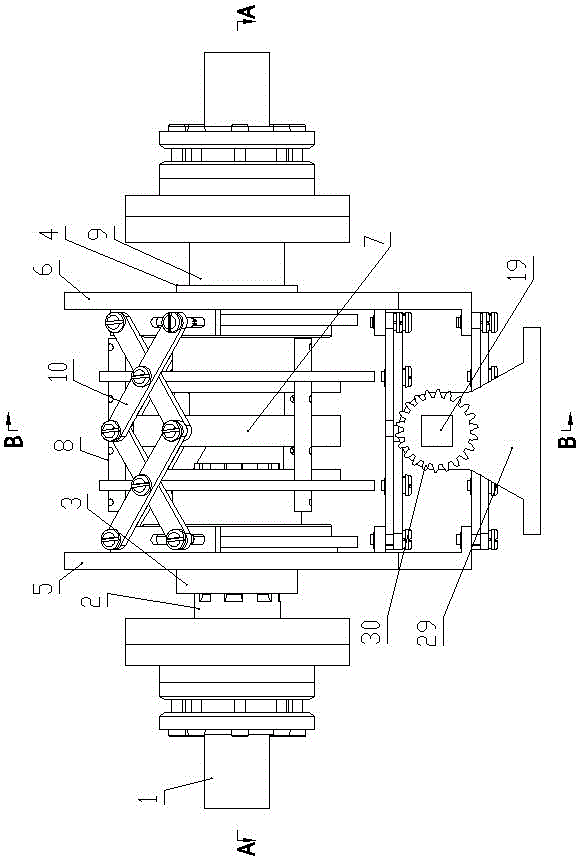
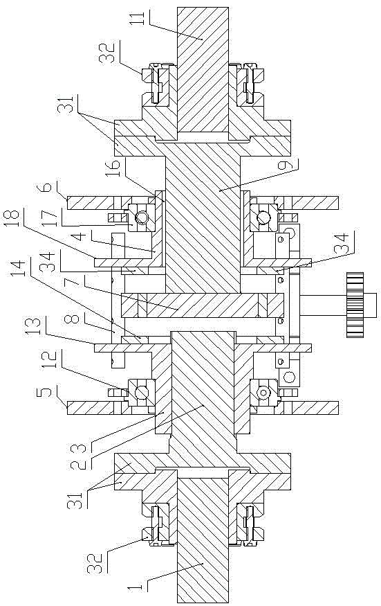
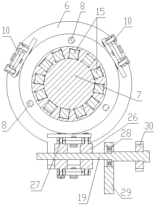
[0048] Such as Figure 1 to Figure 5 As shown, this embodiment provides an adjustable speed permanent magnet coupling, including a power input shaft 1, a drive shaft 2, a left sleeve 3, a right sleeve 4, a left control panel 5, a right control panel 6, an aluminum Alloy bearing disk 7, torque transmission shaft 8, driven shaft 9, parallelogram four-bar mechanism 10 and power output shaft 11;

[0049] The power input shaft 1 is connected to the driving shaft 2 through the first coupling structure, the left sleeve 3 is fixedly sleeved on the driving shaft 2, and the middle part of the left sleeve 3 is equipped with a first bearing 12, and the first bearing 12 is installed with a The left control panel 5 is described; the radial protrusion of the right end of the left sleeve 3 is provided with a left mounting plate 13, and a left copper ring 14 is installed on the right end surface of the left mounting plate 13;

[0050] The bearing disk 7 is fixedly connected to the left end of...

Embodiment 2

[0070] Such as Figure 6 As shown, the difference between this embodiment and Embodiment 1 is that the speed regulating mechanism is different.

[0071] The speed regulating mechanism includes a first threaded sleeve 35 arranged at the bottom of the left control panel 5, a second threaded sleeve 36 arranged at the bottom of the right control panel 6, and passing through the first and second threaded sleeves 35, 36 and The threaded speed regulating shaft 19 which is threadedly connected with the first and the second threaded sleeves 35 and 36 respectively.

[0072] The threaded speed regulating shaft 19 is bounded by the middle part, and the external threads on both sides of the middle part are in the opposite direction. The external thread on the other side of 19 is compatible with the internal thread of the second threaded sleeve 36; the external thread is an existing conventional technology, and the two sections of external thread on the thread speed regulating shaft 19 are...

Embodiment 3

[0079] Such as Figure 7 As shown, the difference between the present embodiment and the second embodiment lies in that the speed regulating mechanism is different.

[0080] The speed regulating mechanism is a gear pair speed regulating mechanism, including a first threaded sleeve 35 arranged at the bottom of the left control panel 5, a second threaded sleeve 36 arranged at the bottom of the right control panel 6, and a bevel gear speed regulating device;

[0081]The bevel gear speed regulating device includes a lower bevel gear 37, a left bevel gear 38 and a right bevel gear 39 installed in the gear box 42. The left bevel gear 38 is located on the left side of the lower bevel gear 37 and is meshed with the lower bevel gear 37. The bevel gear 39 is located on the right side of the lower bevel gear 37 and is meshed with the lower bevel gear 37;

[0082] The left bevel gear 38 is connected with the left speed regulating shaft 40, the right bevel gear 39 is connected with the ri...


PUM


Abstract

The invention discloses a permanent magnet coupler with a speed-adjustable gear pair. The permanent magnet coupler with the speed-adjustable gear pair comprises a power input shaft, a driving shaft, a left sleeve, a right sleeve, a left control panel, a right control panel, a magnet bearing disk, a moment transmission shaft, a driven shaft, a parallelogram four-bar mechanism and a power output shaft. The driving shaft is fixedly sleeved with the left sleeve. A radial protrusion at the right end of the left sleeve is provided with a left installing disk. A left copper ring is installed on the right end face of the left installing disk. A radial protrusion at the left end of the right sleeve is provided with a right installing disk. The moment transmission shaft is connected between the left installing disk and the right installing disk. The parallelogram four-bar mechanism is connected between the top of the left control panel and the top of the right control panel. A gear pair speed adjusting mechanism is connected between the bottom of the left control panel and the bottom of the right control panel. The gear pair speed adjusting mechanism comprises a first threaded sleeve, a second threaded sleeve and a bevel gear speed adjusting device. The permanent magnet coupler capable of adjusting speed well solves problems existing in the prior art and has the advantages of being simple and compact in structure, convenient to install and adjust, not prone to eccentricity, suitable for low-power occasions and the like.

Description

technical field [0001] The invention relates to the technical field of mechanical transmission, in particular to a permanent magnet coupling. Background technique [0002] The permanent magnet coupling is a torque transmission device, which was first used in naval ships and is a revolutionary new technology. [0003] The principle of the permanent magnet coupling is to realize the torque transmission from the motor to the load through the air gap between the copper / aluminum conductor and the permanent magnet. Its main structure is: a magnetic rotor assembly, composed of several rare earth permanent magnets, connected to the load side; copper / aluminum conductor rotor assembly, connected to the motor side. [0004] Permanent magnet couplings can be widely used in power generation, metallurgy, petrochemical, water treatment, mining and cement, pulp and paper, HVAC, shipping, irrigation and other industries for energy saving. In the above industries, the application types are ...

Claims


Application Information

Patent Timeline
Patent Type & Authority Patents(China)
IPC IPC(8): H02K51/00
Inventor 张建立邰志恒杨健李延民李森李峰马胜钢
Owner ZHENGZHOU UNIV
Learn More