
Quick argon feeding method for air separation device

An air separation and rapid technology, applied in liquefaction, coagulation, lighting and heating equipment, etc., can solve the problems of repeated working conditions of argon system, long interval time, and reduced pressure of external pipe network, so as to shorten adjustment time and reduce venting loss. , the effect of improving utilization efficiency

Active Publication Date: 2014-09-03
LAIWU IRON & STEEL GRP
View PDF5 Cites 5 Cited by
  • Summary
  • Abstract
  • Description
  • Claims
  • Application Information

AI Technical Summary

Problems solved by technology

[0005] In the existing operation, the cooling capacity and argon component at the bottom of the crude argon tower II cannot be fully utilized, and the large amount of venting of the crude argon vent valve V712 and the precooling of the circulating liquid argon pump all result in a waste of argon components and cooling capacity. The recovery time of the argon system is extended. During this period, once the working condition of the main tower fluctuates, it is very easy to cause the repetition of the working condition of the argon system
[0006] In the existing operation, the crude argon tower is put into operation first, and then the refined argon tower is put into operation after the oxygen content in the argon drops. After the argon is sent into the hotline pipe network through the product argon pump, since the refined argon tower has not been put into operation, the product argon pump is out of operation and the pressure of the external pipe network is reduced.

Method used


Image

  • Quick argon feeding method for air separation device
  • Quick argon feeding method for air separation device
  • Quick argon feeding method for air separation device

Examples


Embodiment 1

[0040] Attached below figure 2 And embodiment technical scheme of the present invention is described further:

[0041] Example 1

[0042] Take the KDON21000 / 22000 / 750 air separation unit of Laiwu Iron and Steel Group Co., Ltd. as an example.

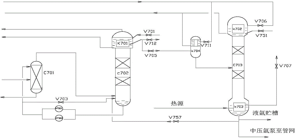
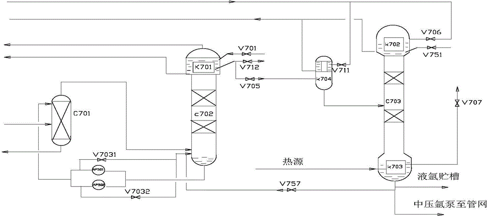
[0043]A rapid argon injection technology for the air separation unit. When the air separation unit is started and the argon tower is put into the argon tower, when the argon fraction is about 6%, the throttle valve V701 of the crude argon condenser can be gradually opened to increase the load of the crude argon condenser K701; start The pre-cooled first circulation liquid argon pump AP501 or the second circulation liquid argon pump AP502, correspondingly, gradually close the first pump return valve V7031 or the second pump return valve V7032, and slowly pump the liquid at the bottom of the crude argon column II C702 Enter the crude argon column IC701, establish the rectification working condition of the crude argon column, during this...


PUM


Abstract

The invention belongs to the technical field of air separation. A quick argon feeding method for an air separation device comprises the following steps: 1) closing a coarse argon emptying valve (V712) after the air separation device stops for a short period, and quickly stopping a circulating liquid argon pump; 2) starting the air separation device, and opening a coarse argon condenser throttling valve (V701) of after an argon fraction of a main tower reaches 6 percent; 3) starting the circulating liquid argon pump to enable liquid argon at the bottom of a coarse argon tower II (702) to enter a coarse argon tower I (C701); 4) respectively opening a coarse argon liquefier adjustment valve (V711), a fine argon condenser adjustment valve (V706) and a technical argon adjustment valve (V705), and fully opening a fine argon emptying valve (V751) to enable a fine argon tower to work; 5) opening a backflow valve (V757) to enable liquid argon at the bottom of the fine argon tower (C703) and liquid condensed by a fine argon condenser (K702) to re-participate in rectification. The quick argon feeding method is conductive to improving the backflow ratio of the coarse argon tower II, shortening the argon tower adjustment time and accelerating concentration of argon.

Description

technical field [0001] The invention belongs to the technical field of air separation, in particular, the invention relates to a method for quickly injecting argon into an air separation device. Background technique [0002] After the air separation unit is shut down for a short period of time and then restarted, the purity of oxygen will reach the target quickly according to the adjustment of the working conditions, but the adjustment of the argon system will take a long time. The operation of the refined argon tower is relatively simple, while the operation of the crude argon tower is to establish the normal oxygen-argon rectification working condition in the crude argon tower, that is, the process of argon components slowly accumulating and enriching in the crude argon tower. It is also the reason why the argon system has been put into operation for a long time. [0003] The operation process of argon injection after the short-term shutdown of the existing air separation...

Claims


Application Information

Patent Timeline
Patent Type & Authority Applications(China)
IPC IPC(8): F25J3/04
Inventor 田现德殷楠楠呼维刚沈荣毕京涛康与峰赵莹狄鹏潘新卿
Owner LAIWU IRON & STEEL GRP
Learn More