A discontinuous air guide tube for an axial flow fan

A technology of axial flow fan and air guide tube, which is applied to components of pumping devices for elastic fluids, mechanical equipment, non-variable pumps, etc., and can solve the problem of reducing fan efficiency, increasing wind wheel resistance, and increasing fan Noise and other problems can be achieved to reduce the loss of air volume and air pressure, avoid eddy currents, and avoid internal leakage.

Active Publication Date: 2016-09-07
XIN CHANG COUNTRY SAN XIN AIR CONDITIONING FAN CO LTD
View PDF4 Cites 0 Cited by
  • Summary
  • Abstract
  • Description
  • Claims
  • Application Information

AI Technical Summary

Problems solved by technology

The wall of the existing air guide tube is generally continuous, that is, there is no channel for dividing the air guide tube on the wall, and its simple structure is as follows: figure 1 As shown: when the fan is working, the blades 3 in the air guide tube 5 rotate, and the wind direction a is upward, so that a positive pressure area b is generated at the outlet section of the air guide tube 5, and a negative pressure area is generated at the inlet section of the air guide tube 5 c, the airflow passes through the gap between the tip of the fan blade 3 (or the vane 4 at the tip of the vane) and the air guide tube 5 from the positive pressure zone b to the negative pressure zone c, that is, the phenomenon of internal leakage, and at the same time it will flow on the vane 4 Vortex is generated at the tail, which increases the resistance of the wind wheel. This not only reduces the efficiency of the fan, but also increases the noise of the fan

Method used


Image

  • A discontinuous air guide tube for an axial flow fan
  • A discontinuous air guide tube for an axial flow fan
  • A discontinuous air guide tube for an axial flow fan

Examples


Embodiment Construction

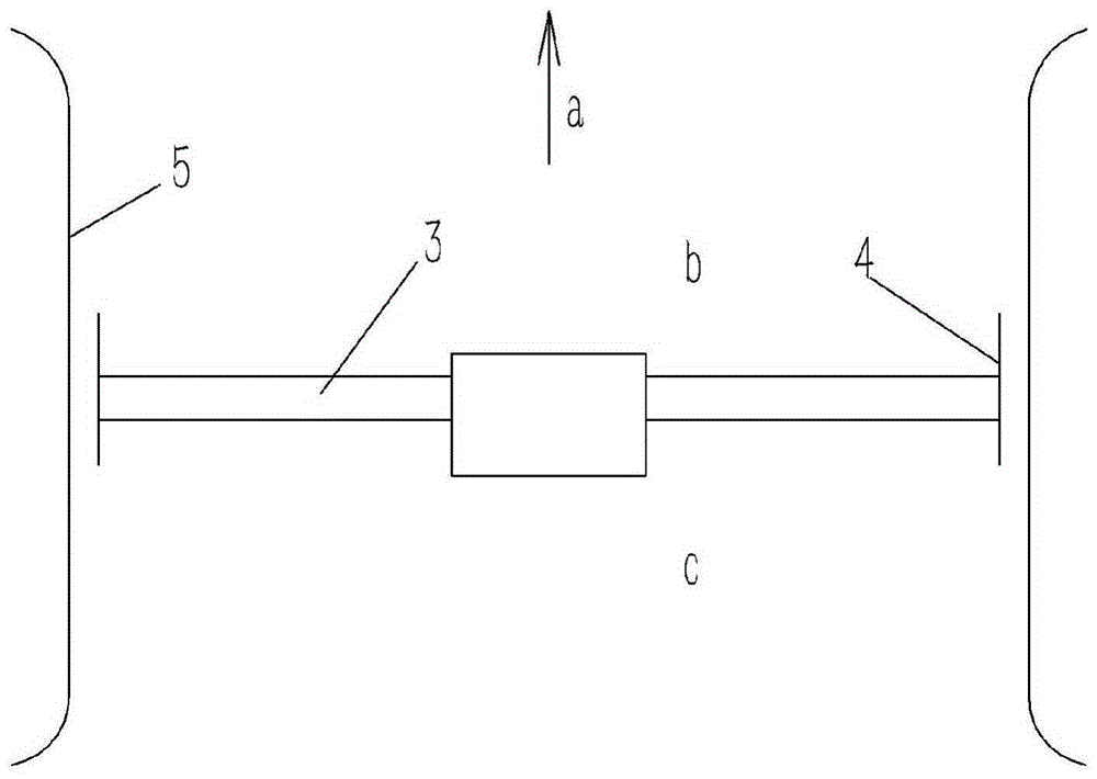
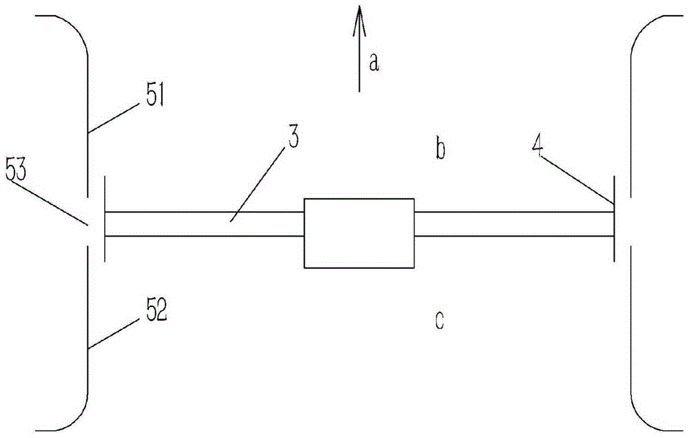
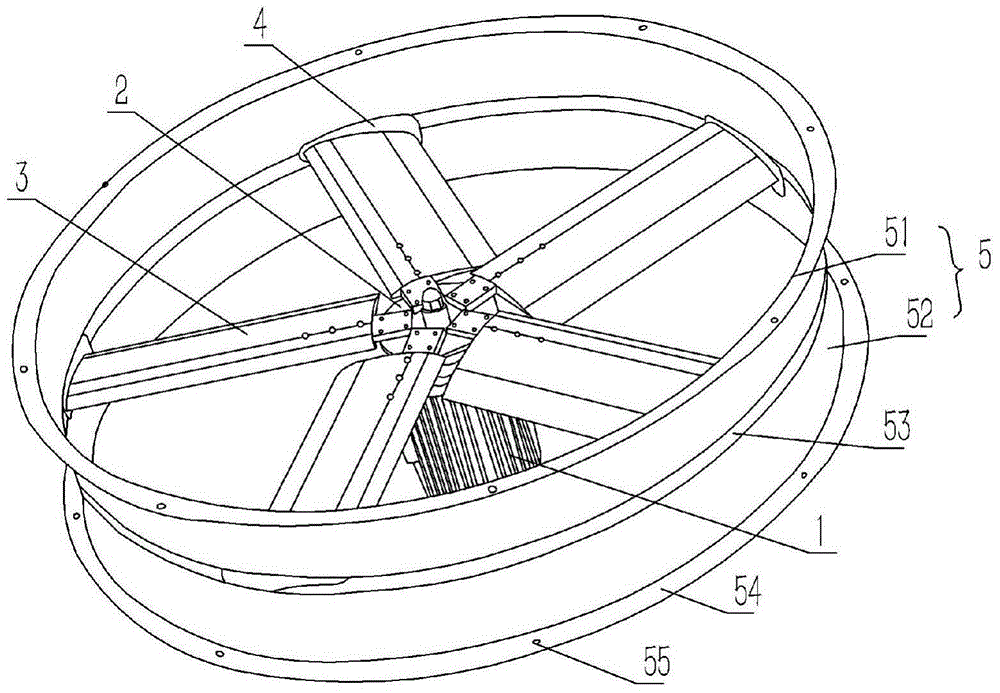
[0020] Example: see figure 2 , 3 As shown, a discontinuous air guide tube of an axial flow fan includes a motor 1 and an air guide tube 5, a rotating disc 2 is fixedly connected to the rotating shaft of the motor 1, and a plurality of fan blades 3 are connected to the rotating disc 2 by bolts. 3. Placed in the air guide tube 5, the upper and lower ends of the air guide tube 5 are formed with outwardly extending flanges 54, and the flanges 54 are formed with bolt holes 55, facing the air guide tube 5 at the outer end of the fan blade 3 An annular slot 53 is formed on the tube wall, and the slot 53 divides the air guiding tube 5 into two upper and lower cylinders of an air outlet tube 51 and an air inlet tube 52 .

[0021] The fan blades 3 are evenly distributed on the turntable 2 in a circular shape, and the outer ends of the fan blades 3 are fixedly connected with the fins 4 , and the slots 53 for dividing the air guide tube 5 are located on the horizontal outer side of the ...


PUM


Abstract

The invention relates to a discontinuous air guiding cylinder of an axial flow fan, comprising a motor (1) and an air guiding cylinder (5). A rotating disk (2) is fixedly connected to the rotating shaft of the motor (1), and a There are several fan blades (3) connected by bolts, and the fan blades (3) are placed in the air guide tube (5), and the upper and lower ends of the air guide tube (5) are formed with outwardly extending flanges (54). Bolt holes (55) are formed on (54), and annular slits (53) are formed on the wall of the air guide tube (5) facing the outer end of the fan blade (3), and the cut grooves (53) divide the air guide tube (5) be shaped into two cylinders up and down the air outlet tube (51) and the air inlet tube (51). The slots on the air guide tube facilitate convection between the positive and negative pressure areas formed by the rotation of the fan blades and the atmosphere, thereby reducing the loss of air volume and wind pressure, improving the working efficiency of the fan, and reducing the noise of the fan.

Description

Technical field: [0001] The present invention relates to the technical field of axial flow fans, and more specifically relates to a discontinuous air guide tube of axial flow fans. Background technique: [0002] The air guide tube has the function of guiding the flow direction of the wind, and is often used in conjunction with the fan. The wall of the existing air guide tube is generally continuous, that is, there is no channel for dividing the air guide tube on the wall, and its simple structure is as follows: figure 1 As shown: when the fan is working, the blades 3 in the air guide tube 5 rotate, and the wind direction a is upward, so that a positive pressure area b is generated at the outlet section of the air guide tube 5, and a negative pressure area is generated at the inlet section of the air guide tube 5 c, the airflow passes through the gap between the tip of the fan blade 3 (or the vane 4 at the tip of the vane) and the air guide tube 5 from the positive pressure ...

Claims


Application Information

Patent Timeline
Patent Type & Authority Patents(China)
IPC IPC(8): F04D29/54F04D29/66
Inventor 潘旭光
Owner XIN CHANG COUNTRY SAN XIN AIR CONDITIONING FAN CO LTD
Why Eureka
Try Eureka