
Tool fixture for permanent magnetic high field intensity magnetic filter magnetic system and assembly process thereof

A tooling fixture and assembly process technology, which is applied in the field of magnetic separation, can solve the problems of complex assembly, uneven distribution, and low field strength in the sorting area, and achieve the effects of improving assembly efficiency, high magnetic field strength, and easy assembly

Inactive Publication Date: 2014-09-03
ZHENGZHOU MINERALS COMPOSITIVE UTILIZATION RES INST CHINESE GEOLOGICAL ACAD
View PDF7 Cites 1 Cited by
  • Summary
  • Abstract
  • Description
  • Claims
  • Application Information

AI Technical Summary

Problems solved by technology

[0007] Aiming at the technical problems of low field intensity, uneven distribution and complicated assembly in the sorting area of ​​the magnetic separator in the prior art, the present invention provides a uniform background magnetic induction intensity of each sorting space that can reach more than 1.5T Fixture and its assembly process for the magnetic system of permanent magnet high-field magnetic filter

Method used


Image

  • Tool fixture for permanent magnetic high field intensity magnetic filter magnetic system and assembly process thereof
  • Tool fixture for permanent magnetic high field intensity magnetic filter magnetic system and assembly process thereof
  • Tool fixture for permanent magnetic high field intensity magnetic filter magnetic system and assembly process thereof

Examples


Embodiment Construction

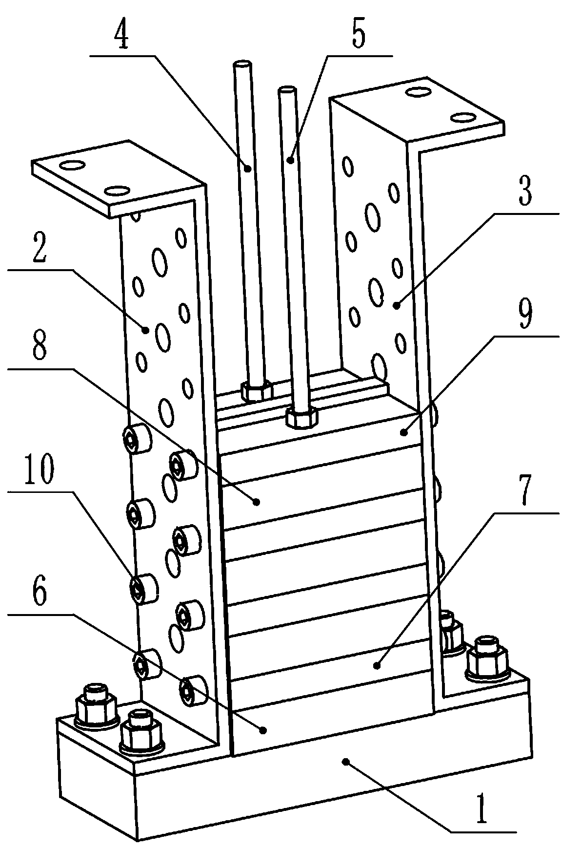
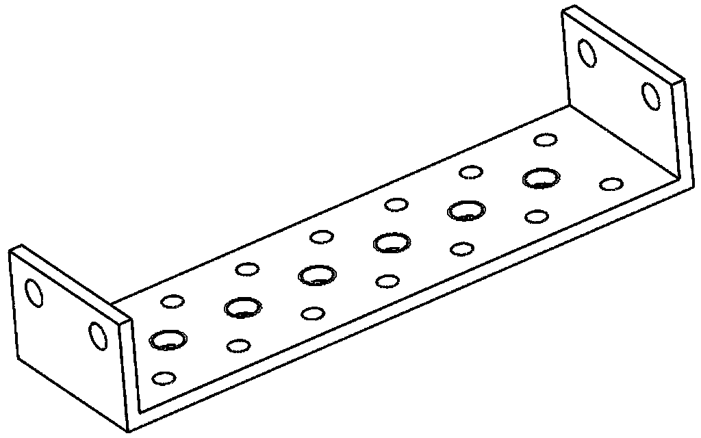
[0028] Such as figure 1 As shown, a tooling fixture for the magnetic system of a permanent magnet high-field magnetic filter includes two magnetic system end plates 1, and a parallel magnetic system armor plate I2 and a magnetic system are fixed between the two magnetic system end plates 1 System armor plate Ⅱ3, between the two magnetic system end plates 1, there are also screw I4 and screw II5, the screw I4 and screw II5 are located between the magnetic system armor plate I2 and the magnetic system armor plate II3. This fixture is for permanent magnets The magnetic block 8 and the magnetic yoke of the high-field magnetic filter are designed for the particularity of the magnetic system. Such as image 3 with Figure 4 For the cross yoke and T-shaped yoke of the permanent magnet high-field magnetic filter magnetic system, the matching method of the magnetic block and the yoke in this application ensures that the uniform background magnetic induction intensity of each sorting spa...


PUM


Abstract

The invention discloses a tool fixture for a permanent magnetic high field intensity magnetic filter magnetic system and an assembly process thereof, and particularly relates to a permanent magnetic high field intensity magnetic system, wherein the even background magnetic induction intensity of each sorting space can reach more than 1.5 T. The tool fixture for the permanent magnetic high field intensity magnetic filter magnetic system and the assembly process thereof aim to solve the technical problems that the field intensity of the sorting area of a magnetic separator is low and uneven in distribution, and assembling is complex in the prior art. The tool fixture for the permanent magnetic high field intensity magnetic filter magnetic system comprises two magnetic system end plates, a magnetic system armor plate I and a magnetic system armor plate II which are parallel are fixed between the two magnetic system end plates, a screw rod I and a screw rod II are further arranged between the two magnetic system end plates, and the screw rod I and the screw rod II are located between the magnetic system armor plate I and the magnetic system armor plate II. By the adoption of the technical scheme, the tool fixture is simple, easy to assemble, convenient to operate and easy to achieve. Although permanent magnet materials with high performance are adopted, assembling is achieved with the help of manpower and auxiliary tool fixtures skillfully, the assembling is complete in a one-off mode, assembling quality is high, magnetic field intensity is high, a magnetic pole is intact in shape, and assembling quality is guaranteed.

Description

Technical field [0001] The invention relates to magnetic separation technology, in particular to a tooling fixture used in the magnetic system of a permanent magnet high-field magnetic filter and its assembly process. Background technique [0002] In recent years, the magnetic system design theory and magnetic pole magnetization technology and equipment have developed rapidly, but there has been little research on the assembly technology of permanent magnet systems, especially high-field permanent magnet systems. In the 1980s, the United States and the United Kingdom The rare earth permanent magnet roller strong magnetic separator with an extruded magnetic system structure has been developed successively, and the corresponding permanent magnetic system assembly research has been carried out. Patent 200910064164.X mentions an assembly process and fixture for the magnetic system of a permanent magnet high-field magnetic filter, which improves assembly quality and efficiency, but th...

Claims


Application Information

Patent Timeline
IPC IPC(8): B25B11/02B23P11/00B03C1/02
CPCB03C1/02B23P11/00B25B11/02
Inventor 张颖新马晓楠于岸洲
Owner ZHENGZHOU MINERALS COMPOSITIVE UTILIZATION RES INST CHINESE GEOLOGICAL ACAD
Learn More