Pump Type Liquid Atomizing Dryer
A liquid atomization and dryer technology, used in spray evaporation and other directions, can solve problems such as low efficiency, small spray volume, particle blockage, etc., and achieve the effects of accelerated evaporation and drying, low energy consumption, and a wide range of applications.
- Summary
- Abstract
- Description
- Claims
- Application Information
AI Technical Summary
Problems solved by technology
Method used
Image
Examples
Embodiment 1
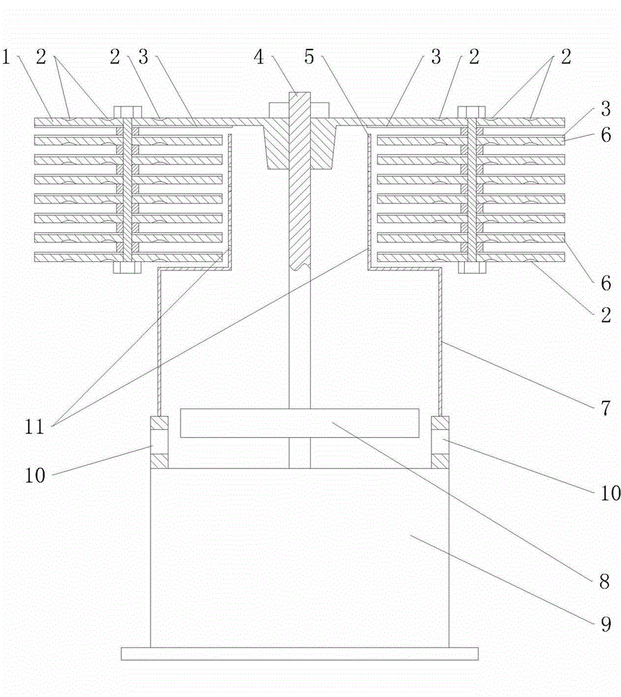
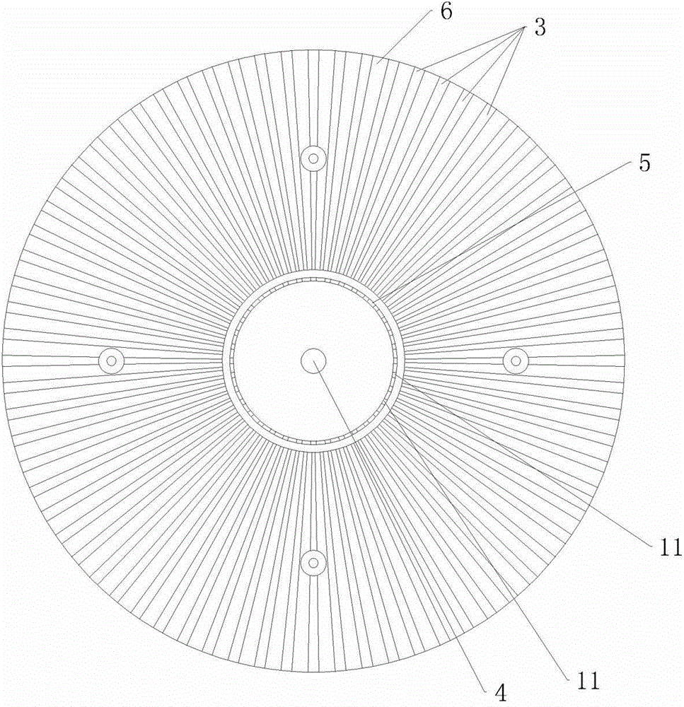
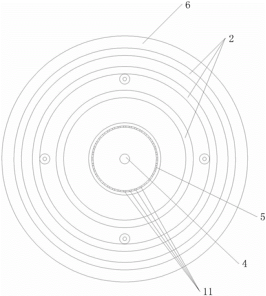
[0027] Embodiment 1: as attached figure 1 To attach image 3As shown, the pump-type liquid atomizing dryer includes a lower casing 7, the lower part of the lower casing 7 is provided with a water inlet 10, and a motor 9 is fixedly connected to the lower casing 7, and the motor 9 is a submersible motor. The upper end of the lower housing 7 is connected with a cylindrical upper housing 5, the upper housing 5 communicates with the lower housing 7 and the water inlet 10, and the output shaft 4 of the motor 9 is connected with an impeller 8 and an upper flywheel 1. The impeller 8 is located in the lower casing 7. The upper flywheel 1 is disc-shaped and located above the upper casing 5. Below the upper flywheel 1, there are seven ring-shaped lower flywheels 6 connected in turn. The lower flywheel 6 surrounds Around the upper casing 5, the upper flywheel 1 and the lower flywheel 6 are arranged horizontally, that is, the inclination angle from the center to the outer circumference is...
Embodiment 2
[0028] Embodiment 2: as attached Figure 4 to attach Image 6 As shown, the pump-type liquid atomizing dryer includes a lower casing 7, the lower part of the lower casing 7 is provided with a water inlet 10, and a motor 9 is fixedly connected to the lower casing 7, and the motor 9 is a submersible motor. A cavity 12 is formed between the motor 9 and the lower casing 7, the upper end of the lower casing 7 is connected with a cylindrical upper casing 5, and the cavity 12 in the upper casing 5 and the lower casing 7 , the water inlet 10 is connected, the output shaft 4 of the motor 9 is connected with an impeller 8 and an upper flywheel 1, the impeller 8 is located in the lower casing 7, and the upper flywheel 1 is a disc type and is located above the upper casing 5, the The bottom of the upper flywheel 1 is connected with seven ring-shaped lower flywheels 6 in turn, and the lower flywheel 6 surrounds the upper casing 5. The upper flywheel 1 and the lower flywheel 6 are inclined...
Embodiment 3
[0029] Embodiment 3: as attached Figure 7 to attach Figure 9 As shown, the pump-type liquid atomizing dryer includes a lower casing 7, the upper end of the lower casing 7 is connected with a cylindrical upper casing 5, and the lower part of the lower casing 7 is provided with a water inlet 10. The lower housing 7 is fixedly connected with a motor 9, and the motor 9 is a submersible motor. A cavity 12 is formed between the motor 9 and the lower housing 7, and the cavity 12 in the upper housing 5 and the lower housing 7 , the water inlet 10 is connected, the output shaft of the motor 9 includes an upper output shaft 41 protruding from the top and a lower output shaft 42 protruding from the bottom, the lower output shaft 42 is fixedly connected with the impeller 8, and the upper output shaft 41 is fixed A disk-shaped upper flywheel 1 is connected, and the upper flywheel 1 is located above the upper casing 5. Below the upper flywheel 1, there are seven ring-shaped lower flywhee...
PUM
 Abstract
Description
Claims
Application Information
 - R&D Engineer
- R&D Manager
- IP Professional
- Industry Leading Data Capabilities
- Powerful AI technology
- Patent DNA Extraction
Browse by: Latest US Patents, China's latest patents, Technical Efficacy Thesaurus, Application Domain, Technology Topic, Popular Technical Reports.
© 2024 PatSnap. All rights reserved.Legal|Privacy policy|Modern Slavery Act Transparency Statement|Sitemap|About US| Contact US: help@patsnap.com


