
Method and device for maching longitudinal edges of metal workpieces

A technology for longitudinal edges, metal workpieces, applied in the direction of workpieces, metal processing equipment, manufacturing tools, etc., to achieve the effect of increasing the feed rate

Inactive Publication Date: 2014-08-27
约瑟夫·波米卡切克
View PDF5 Cites 0 Cited by
  • Summary
  • Abstract
  • Description
  • Claims
  • Application Information

AI Technical Summary

Problems solved by technology

However, the machined surface is corrugated following the cutting arc, which may necessitate the need for remachining

Method used


Image

  • Method and device for maching longitudinal edges of metal workpieces
  • Method and device for maching longitudinal edges of metal workpieces
  • Method and device for maching longitudinal edges of metal workpieces

Examples


Embodiment Construction

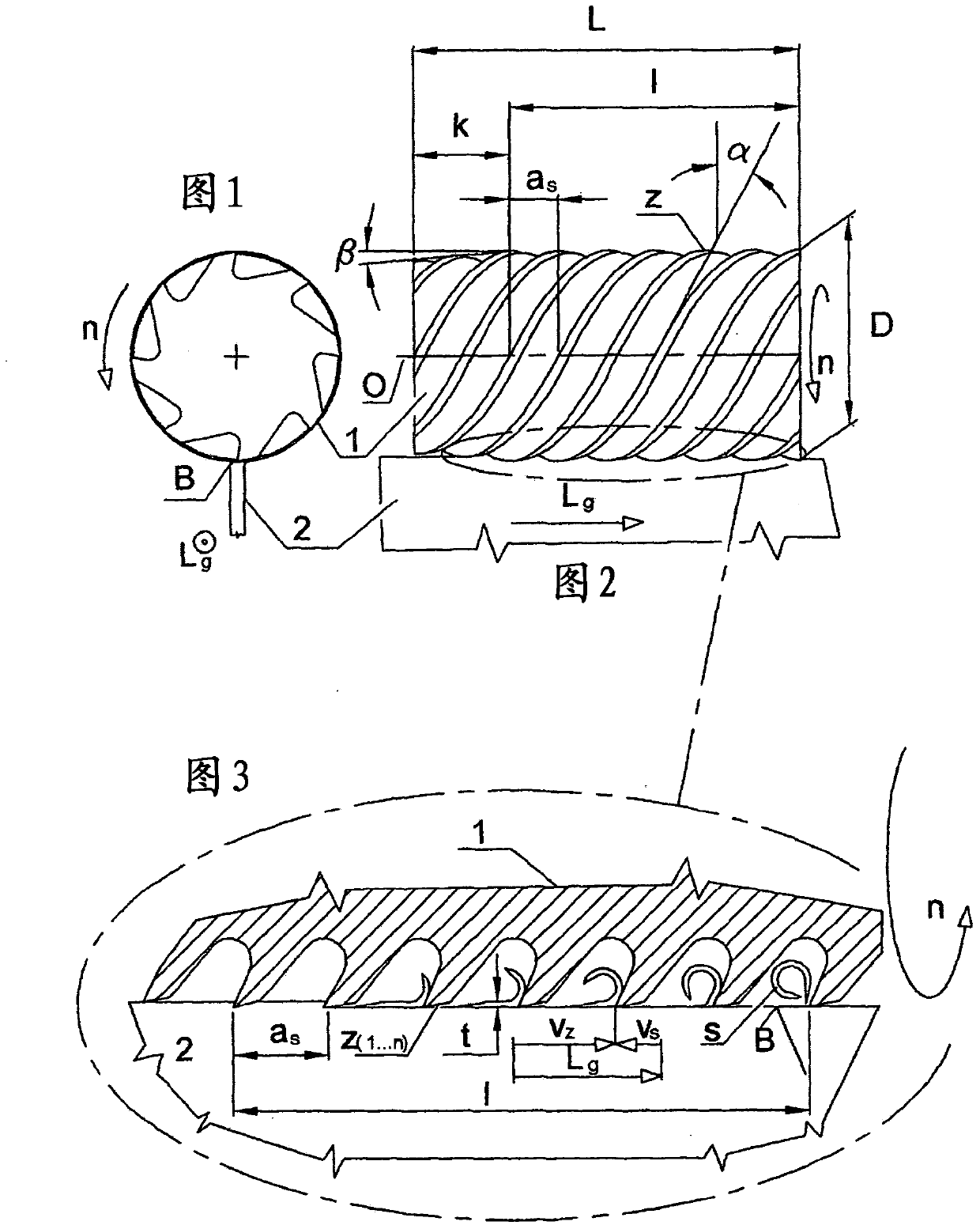
[0019] exist figure 1 A circumferential milling cutter 1 according to the invention and a workpiece 2 are schematically shown in front view.

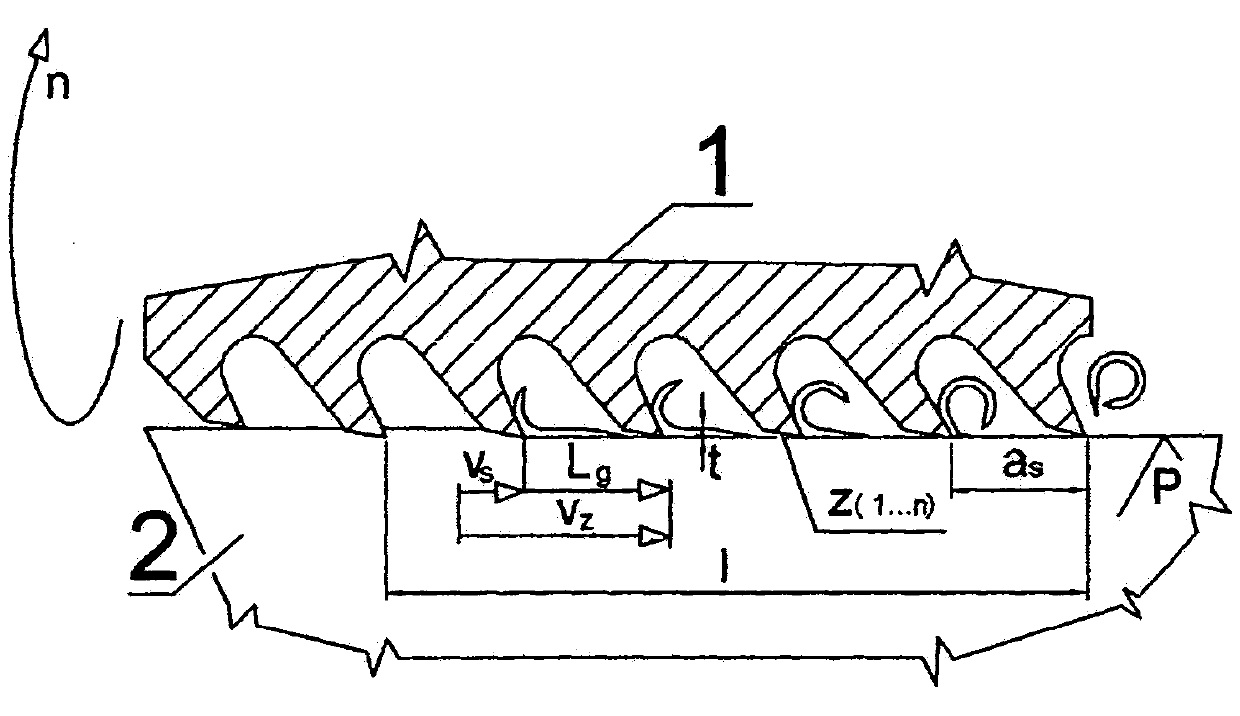
[0020] figure 2 shown in a schematic top view at figure 1 A circumferential milling cutter 1 and a workpiece 2 according to the invention are shown in FIG. The axis of rotation O of the cylindrical peripheral milling cutter 1 is arranged parallel to the machining surface B in such a way that all helically formed cutting edges z interact with the machining surface B over a length l at the same time. The cutting edges are each multi-linear in such a way that they have a helix angle α such that a uniform tooth distance a exists between the individual cutting edges z. s . Circumferential milling cutter 1 in direction of feed L g In the region of one side of the length k, the angle β is conical in order to ensure a smooth action of the cutting edge from the non-cutting state.

[0021] The circumferential milling cutters each comprise ...


PUM


Abstract

The invention relates to a method and device for machining longitudinal edges of metal workpieces (2), wherein, during the machining of the workpiece (2), all of the cutting edges (z) are brought into engagement with the machining surface (B) over an effective length (1) and at a cutting depth (t), and the chips are detached in each case over a length, which corresponds to the tooth spacing (as), between the adjacent teeth simultaneously with the movement thereof along the effective length (1).

Description

technical field [0001] The invention relates to a method and a device for machining longitudinal edges of metal workpieces, said device having a peripheral milling cutter formed by helical cutting edges. Background technique [0002] It is known to machine longitudinal edges of workpieces by means of circumferential milling cutters. According to the prior art, this task is solved in conjunction with high cutting speeds and long chips. Cutting speeds are usually significantly higher than feed rates. The practically achievable feed speeds are generally below 100 m / min, which is partly associated with a poor service life and low economic efficiency. There is a need in several fields of use for increased feed rates and improved economy. The simultaneously active teeth of the known workpiece contact the workpiece at different depths of cut and move along a cutting arc. As a result, the machined surface is provided with flutes, which frequently lead to disadvantages in terms o...

Claims


Application Information

Patent Timeline
Patent Type & Authority Applications(China)
IPC IPC(8): B23C3/12
CPCB23C2265/08B23C5/04B23C3/12B23C3/005B23C2210/0485Y10T407/1946Y10T407/195Y10T407/1954Y10T407/196Y10T409/303752Y10T409/303808Y10T409/304144B23C2215/32B23C2220/00E01B31/13
Inventor 约瑟夫·波米卡切克
Owner 约瑟夫·波米卡切克
Learn More