
Discharge device for rotary hearth furnace

A rotary hearth furnace and discharge technology, which is applied to furnaces, furnace types, furnace components, etc., can solve the problems of low discharge efficiency, dirty discharge, and low service life, so as to increase the discharge area and improve discharge efficiency. Material effect, the effect of improving the service life

Inactive Publication Date: 2014-08-27
NFC (SHENYANG) METALLURGICAL MACHINERY CO LTD
View PDF8 Cites 2 Cited by
  • Summary
  • Abstract
  • Description
  • Claims
  • Application Information

AI Technical Summary

Problems solved by technology

[0003] Due to the characteristics of the spiral structure, it is easy to cause high-temperature materials to scatter to both sides, making the discharge unclean.
The screw operates at high temperature, wears quickly and has a low service life
When the material particles change greatly or the spiral blade wears seriously, the scattered material will cause the problem of dirty discharge and low discharge efficiency; and when the distance between the spiral blade and the hearth of the rotary hearth furnace is large, the residual material will stick On the hearth, the hearth is raised, causing problems such as jamming and shutdown and affecting thermal efficiency
[0004] The patent number is 200810238515.X, and the name is "High Temperature Material Conveying Screw". It discloses a rotary hearth furnace material conveying screw. Water cooling; although this water cooling method can prolong the service life of the screw to a certain extent, the water cooling of the screw blade will cause the thickness of the blade to be too large and the discharge effect will not be good; moreover, the connection between the screw blade and the shaft Sealing, as well as the waterway sealing between the blades are difficult to achieve; this not only greatly increases the difficulty of manufacturing, but also has low economic benefits
[0005] In addition, the existing spiral water cooling usually needs to customize a special rotary joint; this increases the production cost, and requires frequent maintenance and repair of the rotary joint, which is inconvenient to use

Method used


Image

  • Discharge device for rotary hearth furnace
  • Discharge device for rotary hearth furnace
  • Discharge device for rotary hearth furnace

Examples


Embodiment Construction

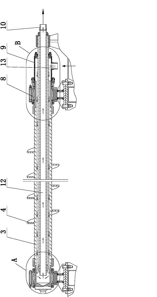
[0020] The present invention includes a first water-cooled screw 5 , and a second water-cooled screw 6 is arranged relative to the first water-cooled screw 5 .

[0021] Both ends of the first water-cooled screw 5 and the second water-cooled screw 6 are arranged on the lifting platform 2 connected with the hydraulic cylinder 11 .

[0022] A scraper 7 is arranged on the side of the first water-cooled screw 5 or the second water-cooled screw 6 . The scraper 7 can gather the scattered materials to the first water-cooled screw 5 or the second water-cooled screw 6, so that the first water-cooled screw 5 or the second water-cooled screw 6 can smoothly discharge the materials, and at the same time, the scraper 7 plays the role of clearing the material to avoid Hearth stick.

[0023] The scraper 7 is set as an arc-shaped tooth structure, through the arc-shaped teeth, materials of appropriate size can pass through to avoid jamming

[0024] The scraper 7 is also arranged on the lifting...


PUM


Abstract

The invention discloses a discharge device for a rotary hearth furnace and relates to an improved structure of a water-cooling spiral discharge device for the rotary hearth furnace. The discharge device for the rotary hearth furnace comprises a first water-cooling spiral part, and is characterized in that a second water-cooling spiral part is opposite to the first water-cooling spiral part. The discharge device for the rotary hearth furnace has the advantages that the structure is simple, production and machining are easy and convenient, and the service life is long.

Description

technical field [0001] The invention relates to an improvement of the structure of a water-cooled spiral discharge device for a rotary hearth furnace. Background technique [0002] The characteristic of the rotary hearth furnace is that the hearth rotates, the material and the hearth are relatively static and evenly distributed on the hearth, and the material layer is relatively thin. The existing discharge is a single-screw discharge, and the high-temperature material is continuously discharged along the forward direction of the helix as the single-screw blade rotates. [0003] Due to the characteristics of the spiral structure, it is easy to cause high-temperature materials to scatter to both sides, making the discharge unclean. The screw operates at high temperature, wears quickly and has a low service life. When the material particles change greatly or the spiral blade wears seriously, the scattered material will cause the problem of dirty discharge and low discharge e...

Claims


Application Information

Patent Timeline
Patent Type & Authority Applications(China)
IPC IPC(8): F27B13/06F27D3/08
Inventor 李英杨占凯伊英红张春晓李建华张世军刘刚黄浩张伟杨志
Owner NFC (SHENYANG) METALLURGICAL MACHINERY CO LTD
Learn More