
Parking mechanism of automobile transmission

A technology of automobile transmission and parking mechanism, which is applied in the direction of instruments, controlled components, mechanical equipment, etc., and can solve problems such as high parts precision requirements, shell damage, transmission failure, etc.

Active Publication Date: 2014-08-27
GREAT WALL MOTOR CO LTD
View PDF6 Cites 22 Cited by
  • Summary
  • Abstract
  • Description
  • Claims
  • Application Information

AI Technical Summary

Problems solved by technology

Since the parking gear of the parking mechanism is fixed on the transmission housing, its position is at the support point of the transmission shaft, the force generated by the transmission shaft during power transmission and the restraint produced by the parking gear during parking The forces are all borne by the same position of the transmission housing, which is easy to cause damage to the housing and cause transmission failure; in addition, the synchronous meshing mechanism of the parking mechanism adopts an inertial synchronization device, and the parking gear is arranged on one side of the synchronization device, and on the other side of the synchronization device. The power transmission gear is arranged on one side, and the synchronization device moves to the parking gear side during parking, so that the parking gear meshes with the synchronization device. When the vehicle is running normally, the synchronization device moves to the other side, so that the power transmission gear meshes with the synchronization device. Because its synchronization device relies on friction to realize parking brake, the parking effect will become worse and worse with the wear of the friction surface of the corresponding parts, and in order to realize the above functions, the structure of the parking mechanism is complicated, and the parts Higher precision requirements and corresponding increase in cost

Method used


Image

  • Parking mechanism of automobile transmission
  • Parking mechanism of automobile transmission
  • Parking mechanism of automobile transmission

Examples


Embodiment Construction

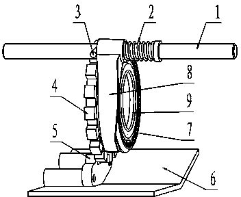
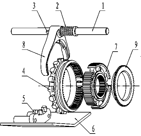
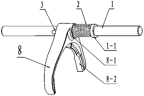
[0023] See Figure 1, figure 2 , image 3 , the present invention includes a shift fork shaft 1, a shift fork 8, a parking gear sleeve assembly 4, a gear hub 7, a parking tooth plate 5 and a synchronizing ring 9, the shift fork shaft 1 is connected with the parking control mechanism, and the The shift fork 8 is composed of a shift fork installation sleeve 8-1 and a claw 8-2. The shift fork installation sleeve 8-2 is set on the shift fork shaft 1 in a clearance fit manner, and rolling or sliding bearings can also be added. To improve the smoothness of fork movement. The claw 8-2 is assembled with the parking gear sleeve assembly 4, and the parking gear sleeve assembly 4 is set on the gear hub 7, and they are connected with the parking gear plate 5 fixed on the bottom surface of the transmission case 6. Matching, the parking gear plate 5 is located on the left side of the parking gear sleeve assembly 4, the gear hub 7 is fixed on the transmission shaft of the transmission, and...


PUM


Abstract

The invention provides a parking mechanism of an automobile transmission. The parking mechanism of the automobile transmission comprises a shifting fork shaft, a shifting fork, a parking gear sleeve assembly, a gear hub, a parking toothed plate and a synchronizing ring; the shifting fork shaft is connected with a parking control mechanism; the shifting fork is composed of a shifting fork mounting sleeve and a clamping jaw; the shifting fork mounting sleeve sleeves the shifting fork shaft in a clearance fit manner; the clamping jaw is assembled with the parking gear sleeve assembly which sleeves the gear hub; the parking gear sleeve assembly is further matched with the parking toothed plate fixed on the bottom surface of a transmission housing; the parking toothed plate is located at the left side of the parking gear sleeve assembly; the gear hub is fixed on a drive shaft of the transmission; the synchronizing ring is mounted at the right side of the parking gear sleeve assembly and matched with drive gears of other gears of the transmission. The parking mechanism of the automobile transmission has the characteristics of simple structure and reliable performance; the manufacturing cost of parts is reduced, and the transmission housing is prevented from being damaged and normal operation of the automobile is guaranteed.

Description

technical field [0001] The invention relates to an automobile parking mechanism, in particular to a parking mechanism arranged on an automobile automatic transmission, and belongs to the technical field of automobiles. Background technique [0002] The function of the car parking mechanism is to give the vehicle a resistance to keep it stationary when parking. The main form of the parking brake is the hand brake or the P gear in the automatic transmission. It achieves the purpose of parking on a slope without slipping the car by locking the drive shaft or the rear wheel. [0003] The Chinese invention patent document whose publication number is CN1683811A provides a parking mechanism for a transmission, which includes a transmission housing, a parking gear fixed on the transmission housing, and a meshing mechanism such as a synchronous meshing mechanism. The engaging mechanism includes a connecting sleeve for engaging the parking gear when the connecting sleeve moves axiall...

Claims


Application Information

Patent Timeline
Patent Type & Authority Applications(China)
IPC IPC(8): F16H63/34F16H63/32
CPCF16H63/32F16H63/3433
Inventor 史铭陈晓峰周广冉昭程格刘彦甫
Owner GREAT WALL MOTOR CO LTD
Learn More