Rotational casting mold chain and metallurgy casting machine with same

A technology of casting molds and molding machines, which is applied in mechanical cleaning, manufacturing tools, casting equipment, etc., can solve problems such as warped seams, limit the service life of molds, and burnt molds, so as to improve service life and ensure safe, continuous and stable operation Effect

Inactive Publication Date: 2014-08-27
北京意通科技有限公司
View PDF8 Cites 0 Cited by
  • Summary
  • Abstract
  • Description
  • Claims
  • Application Information

AI Technical Summary

Problems solved by technology

In the production process, mold sticking caused by casting burrs intruding into the gap often occurs, and there is slag inclusion in the process of opening and closing of the butt joint surface of the casting mold, resulting in seam warping
When mold sticking and slag inclusion problems occur, the chain-type metallurgical casting machine cannot self-clean and solve it, resulting in the need to stop midway to clean the casting mold, resulting in a decrease in production efficiency, and even condensation of high-temperature liquid in the casting tank
If the cleaning is not timely or thorough, starting the casting again will lead to problems such as missing molds and burning molds, resulting in damage to the machine and poor stability in continuous production
[0005] 2. Since the butt joint surfaces between the casting molds are at right angles, during the long-term high-temperature casting process, the high temperature difference between the side wall of the casting mold and the bottom of the casting mold will cause the casting mold to gradually bend and deform, and will gradually Create a gap between right-angled mating surfaces
This will also cause mold leakage and mold burning, resulting in the need to clean the mold or even replace the mold, which limits the service life of the mold
[0006] In short, because of the poor safety, stability and low life of the chain metallurgical casting machine, it has not been widely used in practice.
At present, nickel, chromium, manganese and other 20mm-70mm sections, blocks, and granules in the metallurgical industry are still produced by manpower crushing, machine crushing, and water quenching, which has high labor intensity, large dust particles, and high waste.

Method used


Image

  • Rotational casting mold chain and metallurgy casting machine with same
  • Rotational casting mold chain and metallurgy casting machine with same
  • Rotational casting mold chain and metallurgy casting machine with same

Examples


Embodiment 1

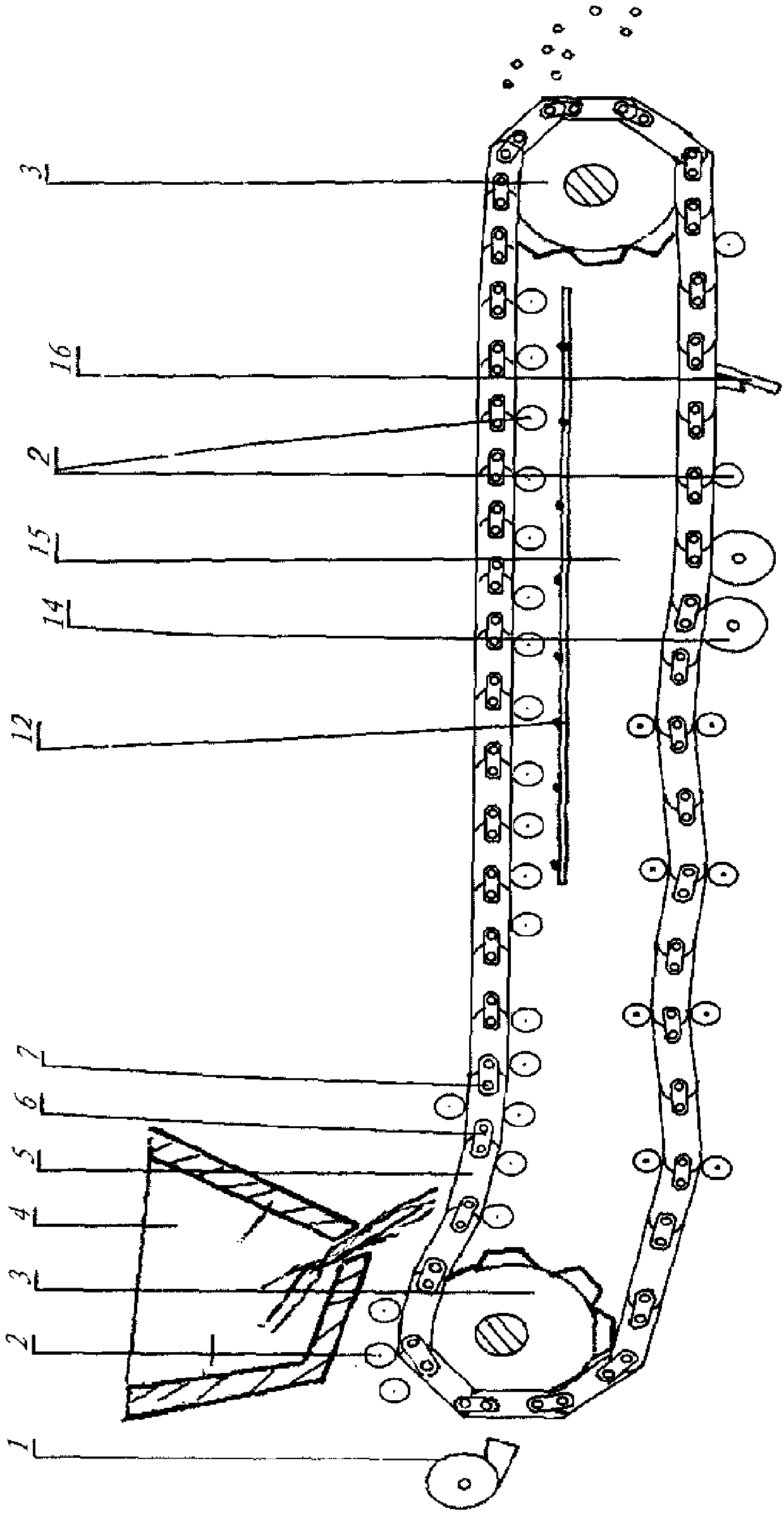
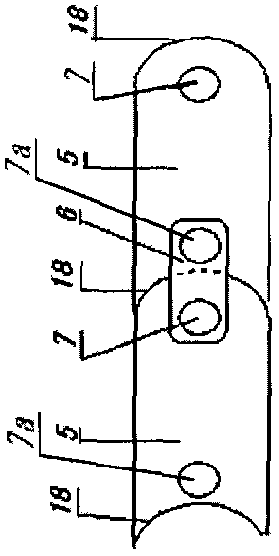
[0025] figure 1 It is a structural schematic diagram of the first embodiment of the metallurgical casting machine. Adjacent casting molds 5 are connected to each other through link plates 6 to form an annular rotary casting mold chain. The casting mold 5 and the link plate 6 are hinged at the chain shaft 7 and fixed at the fixed shaft 7 a, and the casting mold 5 can rotate around the chain shaft 7 . A rotary casting mold chain formed by interlinking a plurality of casting molds 5 and two sprockets 3 located on the upstream and downstream sides are supported by the chain rail frame 15 . The sprocket 3 is driven by an unillustrated motor, thereby pushing the casting mold 5 to rotate, and circulates along a plurality of chain rail rollers 2 fixed on the chain rail frame 15 . A plurality of chain rail rollers 2 play the role of supporting and limiting the turning path of the casting mold 5, and can be arranged separately according to actual needs, as long as the turning path of ...

Embodiment 2

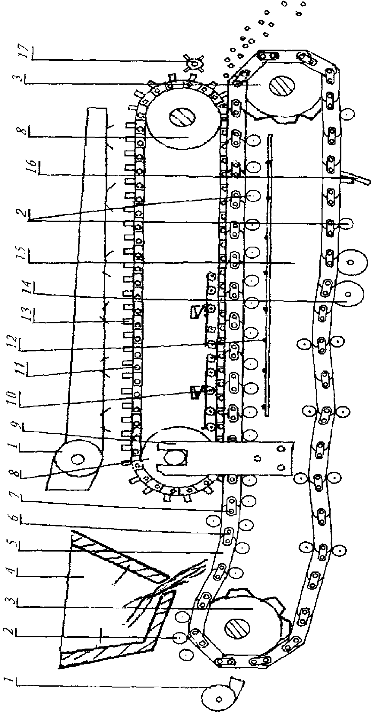
[0028] figure 2It is a structural schematic diagram of the second embodiment of the metallurgical casting machine. The metallurgical casting machine of the second embodiment is also provided with a support wheel 8 and a support wheel frame 9 on the basis of the first embodiment. The support wheel frame 9 supporting the support wheel 8 located on the upstream side is vertically fixed on the chain rail frame 15 . On the two support wheels 8 at the upstream and downstream sides, an endless chain of rotary sizing dies formed by interlinking the sizing dies 13 is encircled. Two support wheels 8 can rotate, and drive the rotary movement of the chain of the rotary shaping die. Adjacent sizing dies 13 are linked to each other at a link axis 11 . The calibrating mold 13 is a convex mould, which has a convex part. During the rotation process, the calibrating mold 13 cooperates with the casting mold 5 in its convexity, synchronously operates to carry out combined molding, and produce...


PUM


Abstract

The invention provides a rotational casting mold chain and a metallurgy casting machine with the rotational casting mold chain. Butt-joint faces between casting molds can be automatically cleaned, it is guaranteed that the butt-joint faces are in close fit, the service life of the casting molds is prolonged, and casting cost is reduced. The rotational casting mold chain is formed by connecting a plurality of casting molds in a chained mode. Each casting mold is provided with an arc butt-joint face. The portion, on one side of each casting mold, of the corresponding arc butt-joint face is of a downwards-recessed arc shape and the portion, on the other side of each casting mold, of the corresponding arc butt-joint face is a of a protruding arc shape. Every two adjacent casting molds are in butt joint in the mode that the corresponding protruding arc is located in the corresponding downwards-recessed arc. Each casting mold is provided with a chain shaft on one side and a fixing shaft on the other side. Every two casting molds are in chain connection through chain connection boards after being in butt joint. The casting molds and the chain connection boards are hinged on the chain shaft portions and fixed on the fixing shaft portions. The radian of the downwards-recessed arc and the radian of the corresponding protruding arc of each arc butt-joint face are identical. After every two casting molds are in butt joint and are in chain connection, the corresponding two casting molds are in sliding contact along the corresponding arc butt-joint faces so that the corresponding two casting molds can relatively rotate with the corresponding chain shaft serving as a circle center.

Description

technical field [0001] The invention relates to a rotary casting mold chain capable of continuously casting various metallurgical castings and a metallurgical casting machine with the same. Background technique [0002] Common in the field of continuous casting is the belt casting machine, which uses a channel casting mold with through grooves for continuous casting of various castings. The through groove of the groove casting mold of the belt molding machine is composed of a side stopper and a belt, and a setting mold composed of a belt and a convex device is arranged on the through groove, which can cast castings of various sizes product. However, since the belt itself is thin and long as a groove casting mold, and the side stopper and the belt are combined into a composite mold, the side stopper and the belt are deformed unevenly when casting high-temperature castings. Due to the different degrees of cold and heat deformation of the side block and the belt, when casting...

Claims


Application Information

Patent Timeline
Patent Type & Authority Applications(China)
IPC IPC(8): B22D11/14B22D11/06B22D43/00
Inventor 杨连虎
Owner 北京意通科技有限公司
Why Eureka
Try Eureka