
Charging circuit for an energy storage device, and method for charging an energy storage device

A technology of an energy storage device and a charging circuit, which is applied to the charging circuit for an energy storage device and the field of charging an energy storage device, can solve problems such as increasing costs and structural space, and achieve reduction of structural space, simplification of system topology, The effect of reducing the range of variation

Inactive Publication Date: 2014-08-20
ROBERT BOSCH GMBH
View PDF10 Cites 4 Cited by
  • Summary
  • Abstract
  • Description
  • Claims
  • Application Information

AI Technical Summary

Problems solved by technology

But this is associated with increased costs, construction space and material usage

Method used


Image

  • Charging circuit for an energy storage device, and method for charging an energy storage device
  • Charging circuit for an energy storage device, and method for charging an energy storage device
  • Charging circuit for an energy storage device, and method for charging an energy storage device

Examples


Embodiment Construction

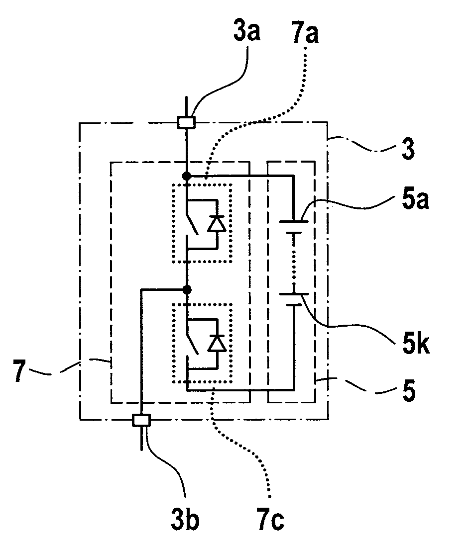
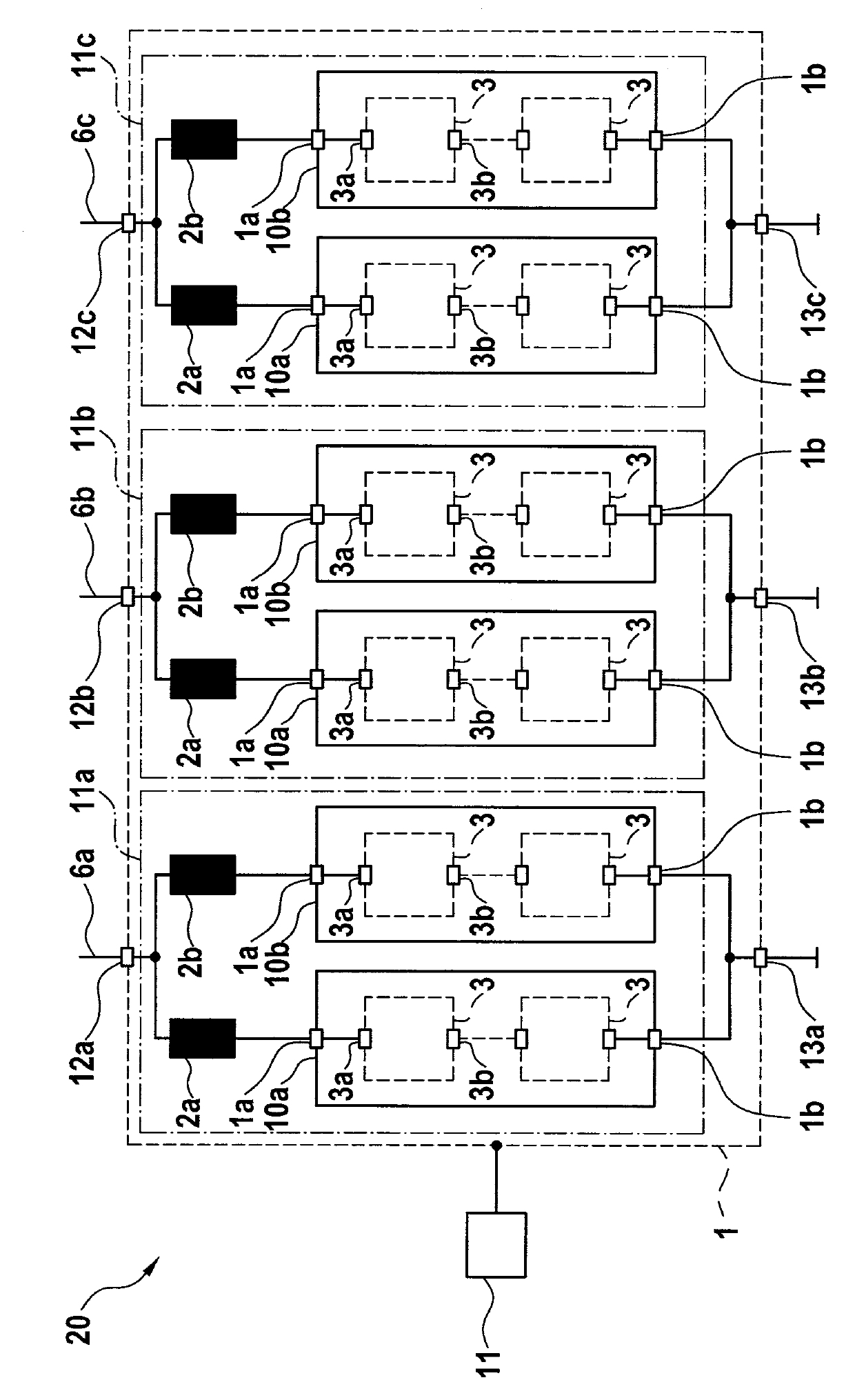
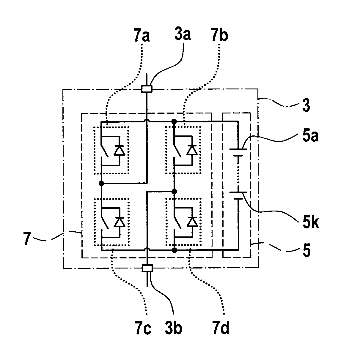
[0030] figure 1 An energy storage device 10 is shown with a battery module 1 for providing a supply voltage via parallel-connectable energy supply branches 10 a , 10 b between two output terminals 4 a and 4 b of the energy storage device 10 . The energy supply branches 10a, 10b each have a branch connection 1a and 1b. The energy storage device 10 has at least two energy supply branches 10a, 10b connected in parallel. The number of energy supply branches 10a, 10b is for example in figure 1 Among them are two, but any other larger number of energy supply branches 10a, 10b is likewise possible. Here, too, it is also possible to connect only one energy supply branch 10 a between the branch connections 1 a and 1 b , which in this case form the output connections 4 a , 4 b of the energy storage device 10 .

[0031]In this case, the energy supply branches 10 a , 10 b can be coupled to the output terminal 4 a of the energy storage device 10 via storage inductances 2 a , 2 b respect...


PUM


Abstract

A charging circuit for an energy storage device having an inductive transmitter element designed to inductively receive a charging AC voltage. In one embodiment, a rectifier is coupled to the inductive transmitter element and designed to convert the received charging AC voltage into a charging DC voltage. The energy storage device has at least one energy supply section coupled between two output connections of the energy storage device. The energy supply section has one or more energy storage modules connected in series in the power supply section. The energy storage modules each have an energy storage cell module having at least one energy storage cell, and a coupling device having a large number of coupling elements.

Description

technical field [0001] The invention relates to a charging circuit for an energy storage device and a method for charging an energy storage device, in particular a method for charging a battery direct inverter circuit and a battery converter circuit, wherein the battery direct inverter The electric circuit and the battery converter circuit are used, for example, in electric drive systems of electrically operated vehicles. Background technique [0002] It seems that in the future there will be increasing use of new energy storage technologies combined with electric drive technology, both in stationary applications such as wind power plants or solar power plants, and in vehicles such as hybrid or electric vehicles. electronic system. [0003] To feed alternating current into the electric machine, the direct voltage supplied by the direct voltage intermediate circuit is converted into a three-phase alternating voltage, usually by means of an inverter in the form of a pulse inv...

Claims


Application Information

Patent Timeline
Patent Type & Authority Applications(China)
IPC IPC(8): H02J7/00H02M7/49
CPCH02J7/025H02J7/0048H02J50/10H02J50/12H02J7/02H02J7/00
Inventor P.费伊尔施塔克
Owner ROBERT BOSCH GMBH
Learn More