An optical scanning display and interactive device

An interactive device and optical scanning technology, applied in the field of interactive devices and scanning display, can solve the problems of not considering the needs of other functions of future users, expensive high-speed motors, low mechanical scanning speed, etc., to achieve large-scale benefits. The effect of commercial production, convenient human-computer interaction, and low cost

Inactive Publication Date: 2016-02-24
JILIN UNIV
View PDF5 Cites 0 Cited by
  • Summary
  • Abstract
  • Description
  • Claims
  • Application Information

AI Technical Summary

Problems solved by technology

However, the mechanical scanning speed is low, and it is difficult to meet the scanning requirements of high-definition television in the future. The price is also relatively expensive, not only that, but life issues are the reasons why it is difficult to put it on the market for practical use
[0003] In addition, the traditional design idea is only for display, without considering the needs of future users for other functions such as interaction

Method used


Image

  • An optical scanning display and interactive device
  • An optical scanning display and interactive device
  • An optical scanning display and interactive device

Examples


Embodiment 1

[0029] Embodiment 1 Optical scanning display and interactive embodiment

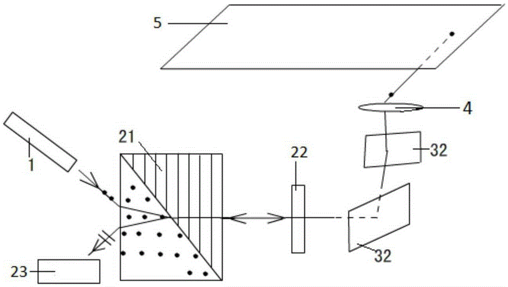
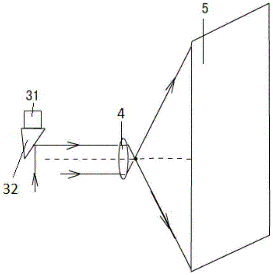
[0030] refer to figure 1 , The display device capable of interactive optical scanning includes a light source 1 and a Wollaston spectroscopic module, a light micro-translation module, a short-focus lens 4 and a receiving screen 5 placed in sequence along the optical path. Wherein the light source 1 is a light source capable of producing linearly polarized thin parallel beams, and the Wollaston spectroscopic module is composed of a Wollaston prism 21, a 1 / 4 wave plate 22 and a photoreceptor 23, and the thin parallel beams emitted from the light source 1 are incident on the One side of Wollaston prism 21 (the side where o and e light are separated), after refraction, emerges from the other side of Wollaston prism 21 (at this time, o and e light overlap together), and vertically pass through 1 After the / 4 wave plate 22 reaches the light micro-translation module. The light micro-translation module is comp...

Embodiment 2

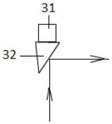
[0035] Embodiment 2 Embodiment of light micro-translation module

[0036] refer to image 3 , the light micro-translation module is composed of a stretchable base and a reflector element. When the base stretches, the reflected light will shift with the original reflected light.

[0037]In addition to the electrostrictive material given in Example 1, the stretchable base of the light micro-translation module can also adopt a structure in which an electromagnet and an armature piece sandwich a layer of elastic material, and the mirror element 32 is fixed with the armature piece. In this way, by changing the current of the electromagnet, its attractive force on the armature piece can be changed, thereby realizing the control of the position of the mirror element 32 .

Embodiment 3

[0038] Embodiment 3 Wollaston light splitting module embodiment

[0039] The o-light and e-light on the left side of the Wollaston prism have a common optical path, and the two optical paths on the right side are separated, so one of the ends of the two separated tubes on the right side can be equipped with a light source 1, and the other branch can be equipped with a photoreceptor 23, 1 The function of the / 4 glass slide 22 is to turn the polarization direction of the light by 90°. It should be noted that the included angle between the vibration plane of the light emitted from the light source 1 and the main section of the 1 / 4 glass slide 22 is 45°.


PUM


Abstract

The invention provides an optical scanning display and interaction device, which belongs to the technical field of optical information display and interaction. The optical scanning display and interaction device structurally comprises a light source (1), a Wollaston light splitting module, a light ray micro translation generation module, a short focal length lens (4) and a receiving screen (5), wherein the Wollaston light splitting module consists of a Wollaston prism (21), a quarter wavelength plate (22) and a light sensor (23) and is used for separating a light path of emergent light from a light path of reflected light and reading reflecting light information; the light ray micro translation generation module can enable light rays to generate micro translation; the short focal length lens (4) is used for enabling the light rays to generate a deflection angle; finally, light spots scanning along with control signals are formed on the receiving screen (5); and the image display is realized. The optical scanning display and interaction device has the advantages that the problems of poor precision, stability control difficulty and the like of optical mechanical scanning are solved; hardware basics for realizing an interaction function are also provided; and when the optical scanning display and interaction device is used for display manufacturing, a touch screen interaction or pointer pen interaction function and a paper document scanning function can be achieved.

Description

technical field [0001] The invention belongs to the technical field of optical information display and interaction, and in particular relates to an interactive device for scanning and displaying. Background technique [0002] Laser TV uses semiconductor-pumped solid-state laser working material to generate continuous laser light with three wavelengths of red, green and blue as the light source of color laser TV, and controls the three-color laser scanning image through TV signals. Its color gamut coverage can theoretically reach more than 90% of the human eye color gamut. This is another notch higher than the highest 62% color gamut coverage of current LED TVs. Not only that, laser TV has many advantages such as realizing rotating screen and 3D effect, but its key technical level scanning deflection is still a problem, so it has not been commercialized for a long time. At present, beam deflection scanning technologies mainly include mechanical scanning, electro-optic scann...

Claims


Application Information

Patent Timeline
Patent Type & Authority Patents(China)
IPC IPC(8): G02B26/10H04N3/08
Inventor 吴香英刘冰冰王广军
Owner JILIN UNIV
Why Eureka
Try Eureka