
Tolerance compensation apparatus

A technology of equipment and tolerance, applied in the field of equipment for tolerance compensation

Active Publication Date: 2014-08-20
WITTE AUTOMOTIVE GMBH
View PDF5 Cites 16 Cited by
  • Summary
  • Abstract
  • Description
  • Claims
  • Application Information

AI Technical Summary

Problems solved by technology

[0003] Known tolerance compensating devices of the above-mentioned type have proven to have a certain degree of disadvantage in that, due to the drive spring, on release of the screw element, the compensating element moves back from its compensating position in the direction of its starting position, for example, again to substantially In the component

Method used


Image

  • Tolerance compensation apparatus
  • Tolerance compensation apparatus
  • Tolerance compensation apparatus

Examples


Embodiment Construction

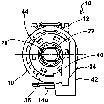
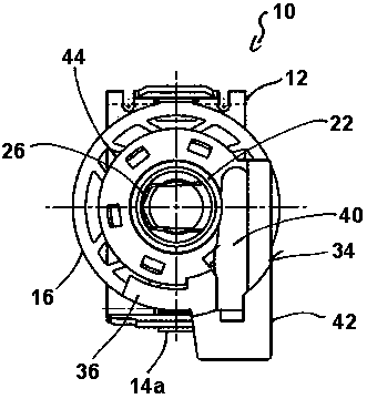
[0035] figure 1 A first embodiment of a tolerance compensation device 10 for compensating tolerances between a first component (not shown) and a second component (not shown) is shown in .

[0036] The tolerance compensation device 10 comprises a snap-in nut 12 made of spring steel and by means of said snap-in nut the tolerance compensation device 10 can be fastened to the first component. In the illustrated embodiment, the snap-in nut 12 is positioned at the lower side of the tolerance compensation device 10 . The snap-in nut 12 comprises a nut element (not shown) for screwing onto a screw element (eg a screw or a threaded bolt) extending through the tolerance compensation device 10 .

[0037] The snap-in nut 12 is suspended at two fastening hooks 14a, 14b ( figure 2 ), said hook is molded onto the fastening ring 16 of the tolerance compensation device 10 ( figure 1 ). The fastening ring 16 is fixedly connected to a base element 18 which is hollow cylindrical and has an i...


PUM


Abstract

The invention relates to an apparatus for the compensation of tolerances between components to be screwed to one another, comprising a hollow-cylindrical base element and a hollow-cylindrical compensation element which is in threaded engagement with the base element and which can be moved from a starting position into a compensation position by rotation relative to the base element. The apparatus is characterized in that a fixing means is provided by which the compensation element can be fixed in the compensation position relative to the base element.

Description

technical field [0001] The invention relates to a device for tolerance compensation between components screwed onto each other, comprising a hollow cylindrical base element and a hollow cylindrical compensating element which is threadedly engaged with the base element and which can be passed relative to the base The rotation of the element moves from the starting position into the compensation position. Background technique [0002] Such tolerance compensation devices are generally known and are used, for example, in automobile construction, precisely when it is the problem of screwing two components onto each other across joint gaps subject to tolerances. Tolerance compensation devices are arranged for this purpose between the components to be connected, and screw elements (eg screws or threaded bolts) for screwing the components together are guided through correspondingly provided openings in the components and through the tolerance compensation equipment. On a screw con...

Claims


Application Information

Patent Timeline
Patent Type & Authority Applications(China)
IPC IPC(8): F16B1/00
CPCF16B5/0283F16B43/009F16B5/0233F16B39/225
Inventor 弗兰克·卢特恩那克劳斯·史毕恩海尔
Owner WITTE AUTOMOTIVE GMBH
Learn More