
Packing box

A packing box and packing technology, which is applied in wellbore/well components, earthwork drilling, sealing/isolation, etc. It can solve problems such as increased workload, increased maintenance costs, sand stuck or wax stuck accidents, etc. , to achieve the effect of prolonging service life, reducing labor load and saving electric energy

Inactive Publication Date: 2014-08-20
TOP WELL PETROLEUM TECH COMPANY
View PDF5 Cites 1 Cited by
  • Summary
  • Abstract
  • Description
  • Claims
  • Application Information

AI Technical Summary

Problems solved by technology

Although engineers and technicians have developed various self-aligning packing boxes, as the pumping unit drives the polished rod to move up and down repeatedly, the polished rod and the sealing packing will wear out for a long time, and the packing box will leak after a period of time, and it needs to be tightened again Packing cap
Due to repeated tightening, the friction between the sealing packing and the polished rod increases, and the pumping unit wastes a lot of electric energy to overcome the useless work generated by this friction
In addition, after tightening to a certain extent, tightening again does not work. At this time, it is necessary to stop the pumping unit and replace the sealing packing, which increases the workload
More importantly, during the shutdown process, the sand contained in the produced oil in the tubing will sink and sink between the oil well pump barrel and the oil well pump plunger. When the packing box is replaced and started twice , Sand stuck or wax stuck accidents often occur, the entire oil well needs to be taken out for inspection, and the maintenance cost is further increased

Method used


Image

  • Packing box

Examples


Embodiment Construction

[0016] The principles and features of the present invention are described below in conjunction with the accompanying drawings, and the examples given are only used to explain the present invention, and are not intended to limit the scope of the present invention.

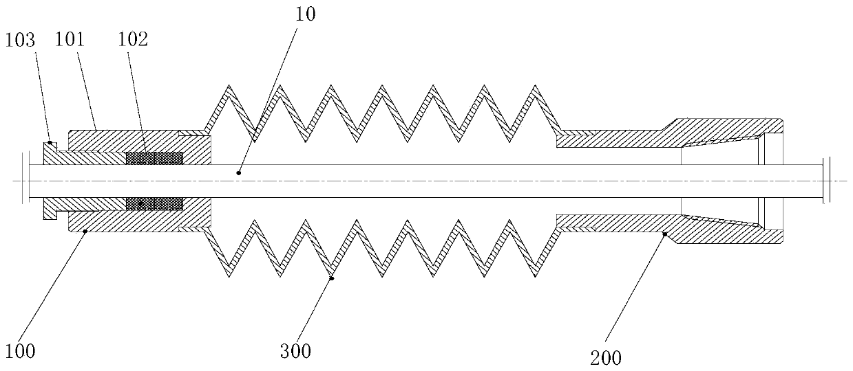
[0017] Such as figure 1 As shown, the present invention provides a packing box, the packing box includes:

[0018] The upper fixed sealing part 100 for fixing on the polished rod 10, the upper fixed sealing part 100 includes a sealing packing box 101 that can be sleeved on the polished rod 10, and a sealing packing box set in the sealing packing box 101 102 and a pressing cap 103 capable of compressing the sealing packing 102 in the sealing packing box 101 so that the sealing packing 102 and the polished rod 10 are hermetically fixed;

[0019] The lower joint 200 used to connect with the wellhead Christmas tree;

[0020] And, the telescopic sleeve 300 that can expand and contract between the upper fixed sealing pa...


PUM


Abstract

The invention provides a packing box. The packing box comprises an upper fixed seal part, a lower connector and a retractable sleeve, the upper fixed seal part is fixed to a polished rod and comprises a seal packing box, seal packing and a pressing cap, wherein the polished rod can be sleeved with the seal packing box, the seal packing is arranged in the seal packing box, and the pressing cap can be used for pressing the seal packing into the seal packing box so that the seal packing and the polished rod can be fixedly sealed. The lower connector is used for being connected with a Christmas tree. The retractable sleeve can retract and stretch between the upper fixed seal part and the lower connector so that the distance between the upper fixed seal part and the lower connector can be changed. The first end of the retractable sleeve is connected with the seal packing box in a sealed mode, and the second end of the retractable sleeve is connected with the lower connector in a sealed mode. According to the packing box, a sliding seal part is not needed, the packing box will not be abraded, and therefore the service life of the packing box is greatly prolonged. Meanwhile, the labor amount of workers is reduced, and while the faults of an oil pumping system are reduced, a lot of oil pumping machine electric energy is saved.

Description

technical field [0001] The invention relates to the technical field of wellhead accessories for oil production in oil fields, in particular to a maintenance-free packing box for wellhead sealing during oil production with rods. Background technique [0002] The packing box is a sealing device for the polished rod at the wellhead of the pumping unit, which plays a role in sealing the annular space between the oil pipe and the polished rod during the normal operation of the oil well. In the case of no failure in the pumping well, the most likely problem at the production wellhead is oil leakage from the packing box. Although engineers and technicians have developed various self-aligning packing boxes, as the pumping unit drives the polished rod to move up and down repeatedly, the polished rod and the sealing packing will wear out for a long time, and the packing box will leak after a period of time, and it needs to be tightened again Packing cap. Due to repeated tightening, ...

Claims


Application Information

Patent Timeline
IPC IPC(8): E21B33/03
Inventor 孟兆贤姚小杰陈勋张殿新李宏川
Owner TOP WELL PETROLEUM TECH COMPANY
Learn More